User:Jcreer/SMS:Select Intersecting Objects: Difference between revisions
From XMS Wiki
Jump to navigationJump to search
No edit summary |
No edit summary |
||
| Line 16: | Line 16: | ||
***''Elements'' &ndash This option enables the selection of specific elements within the module and an intersecting object from the drop down tool found directly above it to which changes will be applied. | ***''Elements'' &ndash This option enables the selection of specific elements within the module and an intersecting object from the drop down tool found directly above it to which changes will be applied. | ||
***''Duplicate nodes'' – This option enables the selection of areas within the module where duplicate nodes intersect with specified objects from the drop down tool found directly above it to which changes will be applied. | ***''Duplicate nodes'' – This option enables the selection of areas within the module where duplicate nodes intersect with specified objects from the drop down tool found directly above it to which changes will be applied. | ||
**''Mesh'' – This section allows selecting specific intersecting components within the mesh module to which the final selection will be applied. | **''Mesh'' – This section allows selecting specific intersecting components within the mesh module to which the final selection will be applied. | ||
***''Points'' – | ***''Points'' – | ||
***''Vertices'' – | ***''Vertices'' – | ||
Revision as of 22:30, 24 January 2020
If a feature polygon is defined, it is possible to select nodes or elements in the mesh module or vertices in the data module that are inside or outside of the feature polygon. To access this tool do the following:
- On a map coverage, select a polygon that defines the area to be selected.
- Select the Feature Objects | Select Intersecting Objects command.
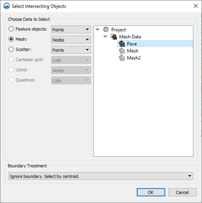
In the dialog that appears, select the geometry that will be using for the selection.
Select Intersecting Objects Dialog
The dialog contains the following options:
- Choose Data to Select – This section allows selecting specific intersecting components within the same module simultaneously with the purpose of selecting specific data where the final selection will be applied. It contains the following options:
- Feature Objects – Selecting this allows a break down of variables within the module that represent specific objects to which changes will be applied.
- Points – This option enables the finding of a point within the module and its intersection with another chosen variable in the drop down selection tool found directly below it to which changes will be applied.
- Vertices – This option enables the selection of an angle within the module and an intersecting object from the drop down selection tool found directly below it to which changes will be applied.
- Arcs – This option enables the selection of a curve within the module and an intersecting object from the drop down selection tool found directly below it to which changes will be applied.
- Polygons – This option enables the selection of a five sided area within the module and an intersecting object from the drop down selection tool found directly below it to which changes will be applied.
- Nodes – This option enables the selection of specific ends to different arcs within the module and an intersecting object from the drop down tool found directly above it to which changes will be applied.
- Elements &ndash This option enables the selection of specific elements within the module and an intersecting object from the drop down tool found directly above it to which changes will be applied.
- Duplicate nodes – This option enables the selection of areas within the module where duplicate nodes intersect with specified objects from the drop down tool found directly above it to which changes will be applied.
- Mesh – This section allows selecting specific intersecting components within the mesh module to which the final selection will be applied.
- Points –
- Vertices –
- Feature Objects – Selecting this allows a break down of variables within the module that represent specific objects to which changes will be applied.
- Scatter
- Cartesian grid
- UGrid
- Quadtree
- Boundary Treatment
SMS – Surface-water Modeling System | ||
|---|---|---|
| Modules: | 1D Grid • Cartesian Grid • Curvilinear Grid • GIS • Map • Mesh • Particle • Quadtree • Raster • Scatter • UGrid |  |
| General Models: | 3D Structure • FVCOM • Generic • PTM | |
| Coastal Models: | ADCIRC • BOUSS-2D • CGWAVE • CMS-Flow • CMS-Wave • GenCade • STWAVE • WAM | |
| Riverine/Estuarine Models: | AdH • HEC-RAS • HYDRO AS-2D • RMA2 • RMA4 • SRH-2D • TUFLOW • TUFLOW FV | |
| Aquaveo • SMS Tutorials • SMS Workflows | ||
