|
|
| Line 30: |
Line 30: |
|
| |
|
| ===Cross Section Other Options=== | | ===Cross Section Other Options=== |
| [[File:CrossSectionOtherOptions.png|thumb|200 px|The Cross Section Other Options dialog]] | | [[File:UGridCrossSectionOtherOptions GMS.png|thumb|200 px|The Cross Section Other Options dialog]] |
| The ''Cross Section Other Options'' dialog is reached through the ''Cross Section Options'' dialog. This dialog contains additional options for adjusting the cross section display. The dialog has the following options: | | The ''Cross Section Other Options'' dialog is reached through the ''Cross Section Options'' dialog. This dialog contains additional options for adjusting the cross section display. The dialog has the following options: |
| *''Cell edges'' – Turn on to display cell edge lines on the cross section. Clicking the button next to this option will open the ''Line Properties'' dialog. | | *''Cell edges'' – Turn on to display cell edge lines on the cross section. Clicking the button next to this option will open the ''Line Properties'' dialog. |
| Line 42: |
Line 42: |
|
| |
|
| {{-}} | | {{-}} |
|
| |
|
| |
|
| ==Related Topics== | | ==Related Topics== |
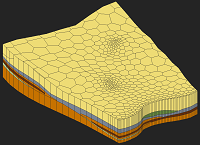
In the UGrid module, the Create Cross Section  tool is used to manually generate cross sections on a unstructured grid. This allows viewing the stratigraphy along the layers of an unstructured grid when rotating the grid.
To use the tool, make sure the UGrid is in plan view then click on one side of the grid followed by click on another side to create a cross section between the two points. When created successfully, a line will appear in the Graphics Window showing the location of the cross section. A cross section item will also appear in the Project Explorer.
Right-click on the cross section item in the Project Explorer has the following menu options:
- Display Options – Opens the Cross Section Options dialog.
- Remove – Deletes the cross section from the project. Removes the cross section from both the Project Explorer and Graphics Window.
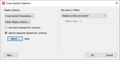
Cross Section Options

The Cross Section Options dialog
The Cross Section Options dialog contain options for how cross sections are displayed. It is reached through the right-click menu of a cross section item in the Project Explorer. The options are only set for the cross section selected when accessing these option.
The dialog has the following options:
- Display Options – This section contains options for changing how the cross section is displayed.
- Cross Section Parameters – Opens the UGrid Cross Section Parameters dialog.
- Other Display Options – Opens the Cross Section Other Options dialog.
- Use active dataset for contours – With this option, contours on the cross section will follow those of the selected active dataset on the UGrid.
- Specify separate dataset for contours – This options allows the user to define which dataset will be used for the contours. This allows the dataset contours of the cross section to be different than the active dataset of the UGrid.
- Select – Open the Select Scalar Dataset dialog where a dataset in the project can be chosen.
- Elevation Z Offset – Options in this section
- "Display surface at location" – Sets the elevation offset to be at the location of the cross section (no offset).
- "Display surface above geometry" – Sets the offset to be just above the geometry elevation.
- "Display surface with user defined offset" – Set the offset to a distance specified by the user.
- Offset value – Enter an elevation Z offset value.
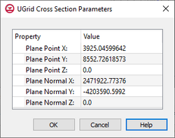
UGrid Cross Section Parameters
The UGrid Cross Section Parameters dialog is accessed through the Cross Section Options dialog. This dialog shows the location values of the cross section.

The UGrid Cross Section Parameters dialog
Cross Section Other Options

The Cross Section Other Options dialog
The Cross Section Other Options dialog is reached through the Cross Section Options dialog. This dialog contains additional options for adjusting the cross section display. The dialog has the following options:
- Cell edges – Turn on to display cell edge lines on the cross section. Clicking the button next to this option will open the Line Properties dialog.
- Cell faces – Turn on to display cell faces on the cross section.
- Points – Turn on to display points along the cross section. Clicking the button next to this option will open the Symbol Attributes dialog.
- Inactive points – Turn on to display inactive points along the cross section. Clicking the button next to this option will open the Symbol Attributes dialog.
- UGrid boundary – Turn on to display grid boundary line on the cross section. Clicking the button next to this option will open the Line Properties dialog.
- Feature angle – Enter the feature angle value for the cross section.
- Face contours – Turn on to see contours on the faces of the cross section. Clicking the button next to this option will open the Contour Options dialog.
- Point contours – Turn on to see contours on the points of the cross section. Clicking the button next to this option will open the Contour Options dialog.
Related Topics


