==Flood Depths Edit
Current article
Flood Depths
This command will create an inundated depth raster. This requires an elevation raster and a water surface elevation dataset. Clicking the command from an elevation raster will bring up a Select Geometry and Dataset dialog where the geometry containing the water surface elevation dataset can be selected. Once the water surface elevation dataset has been specified, the new raster can be saved.
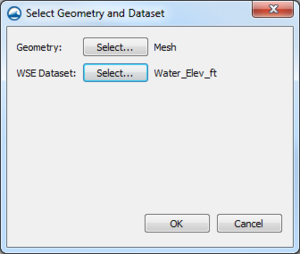
Select Geometry and Dataset dialog for converting a raster to an inundated depth raster
Raster to Flood Depth
| 1. Use raster to calculate flood depths.
|
- This requires an elevations raster and a water surface elevation dataset.
- Right-click on the raster to be used for the flood depths and use the command Convert to|Flood Depths.
- Next to Geometry, select the desired geometry.
- Next to WSE dataset, selet the desired dataset.
- After the tool has finished processing, change the File name as desired in the Save As dialog.
|
First Tests
| TESTSTEESTETE
|
| 1. Convert CAD to Map coverage.
|
- Right-click on the CAD dataset in the Project Explorer and select Convert | CAD → Map.
- Use the options in the Clean Options dialog.
- A new map coverage with converted CAD data will appear in the map module.
|
| 3. Convert CAD points to 2D scatter.
|
- Right-click on the CAD dataset in the Project Explorer and select Convert | CAD Points → 2D Scatter.
- Name the scatter set in the New Scatter Set dialog.
- A new scatter set with converted CAD data will appear in the scatter module.
|
| Nothing in particular
|
|
TEst
|
|
|
| 1. Import CAD data files.
|
- Verify the CAD file type is readable by SMS before importing it. SMS can import DXF and DWG files.
- Use the File | Open... command to launch the Open dialog (or drag and drop) to import the CAD files.
- The data should load in layers into the Project Explorer.
|
| 3. Convert CAD data.
|
| 1. Convert CAD to Map coverage.
|
- Right-click on the CAD dataset in the Project Explorer and select Convert | CAD → Map.
- Use the options in the Clean Options dialog.
- A new map coverage with converted CAD data will appear in the map module.
|
| 3. Convert CAD points to 2D scatter.
|
- Right-click on the CAD dataset in the Project Explorer and select Convert | CAD Points → 2D Scatter.
- Name the scatter set in the New Scatter Set dialog.
- A new scatter set with converted CAD data will appear in the scatter module.
|
|
| 4. Export to CAD Data.
|
- Project data can be converted to CAD data.
- Right-click on an empty space in the Project Explorer and select Convert to CAD.
- Save the CAD data file.
- CAD data will be loaded into the Project Explorer.
|
Interpolating from Multiple Elevation Sources Workflow
| 1. Import elevation sources.
|
| 1. Import rasters.
|
- Raster data is imported into the GIS module in SMS.
- Use the Open command to import raster data files such as DEMs, KMZ files, and gridded elevation formats.
- Files can also be imported with the "drag and drop" option.
|
|
| 3. Interpolate raster elevation to geometry to create new elevation dataset.
|
- The Interpolate Priority Rasters tool allows for multiple rasters to be used when interpolating onto a geometry. To do so, follow these steps:
| 1. Use the Interpolate Priority Rasters tool to interpolate raster data onto the desired geometry.
|
- From the Toolbox, select Interpolate Priority Rasters
- Select the geometry to interpolate onto.
- Select the order of priority for the rasters that will be used for interpolation. The order determines which raster the program will look at first to interpolate data onto the geometry.
- Run the Interpolate Priority Rasters tool.
|
| 2. Review the data on the geometry.
|
- Turn off all rasters.
- Turn on the desired geometry.
- Adjust the Display Options
 . .
|
|
| 4. Set the map elevation dataset to the newly created dataset.
|
- While in the appropriate module for the geometry, use the Data|Map elevation... command.
- Select the newly created dataset.
- Adjust the display as desired to review the change in mapped dataset.
|
Discarded workflow components
| Set unassigned node values.
|
- Depending on the rasters used, it's possible that some mesh nodes didn't get assigned elevation values. To assign them values, follow these steps:
- Right-click on the mesh in the Project Explorer and use the Mesh → 2D Scatter command.
- Select all desired scatter points. ??Include more information on how to do this?
- Delete the selected scatter points and use the Triangles|Triangulate command.
- After switching to the Mesh module, select all nodes with unassigned values in the grid.
- In the Graphics Window, use the Interpolate elevation right-click command.
- Set the Scatter Set To Interpolate From to the scatter set where the unassigned scatter points have just been removed and interpolate it to this scatter set.
|
| Blend Raster Resolution.
|
- Interpolating data from multiple elevation sources first requires blending the rasters involved. To do so, follow these steps:
- From the Toolbox, select Blend Raster to Edges.
- Set the Primary raster and the Secondary raster options with the rasters that are to be blended.
- Specify the distance over which the active edges of the primary raster will be blended into the secondary raster.
- Specify the name of the Output raster. This will be a separate raster created from the primary and secondary raster.
- Run the Blend Raster to Edges tool.
- Examine the newly created raster.
|
| Clip rasters (optional??).
|
- Trimming rasters ensures that no part of the raster is above surveyed elevations. To do so, follow these steps:
|
