SMS:Generic Model Graphical Interface
The Generic Model Graphical Interface includes tools to assist with creating, editing and debugging a Generic Model. The Generic Model interface exists in the Mesh Module.
Define Model
The Define Model dialog is used to customize and define the model interface parameters that define various states and characteristics of a model. These model parameters may include items such as those needed to describe flow, channel roughness, and control structures. The parameters, names, and ranges can be created and customized.
Parameters are organized into groups and are given suitable value ranges depending on the purposes of the model. Proper organization of parameters will increase the abilities of SMS as an interface.
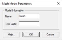
Using the Define Model dialog the model interface can be renamed. The Define Model dialog can be accessed when the Mesh Module is the active module.
The Define Model dialog is used to setup the options that apply to the simulation as a whole.
- Model Parameters
- Global Parameters
- Boundary Conditions
- Material Properties
- Lock Model Definition with Key
Model Parameters
Global Parameters
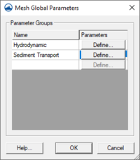
This dialog creates user-defined parameter groups to be used in the project. Each parameter group must be named. Definitions for the group can be set by clicking on the Define button after naming the parameter group. See the Dependencies section for more information.
Boundary Conditions
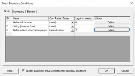
All numeric models require boundary condition (BC) data. Generic Mesh Model boundary conditions can be defined on nodestrings, nodes, and elements. An entity (nodestring, node, or element) may have multiple boundary conditions set. To add or remove a boundary condition, select a node, nodestring, or element. Then right-click and select Assign BC. A dialog with a tree item appears listing all possible boundary conditions. Checked tree items are active boundary conditions. Toggle the tree items as desired to activate/deactivate boundary conditions. The settings in Display | Display Options will determine how the boundary conditions are displayed.
The model developer can define boundary conditions as constant or as dynamic. This is stored in the BD card as the next to last field. It's also possible to assign multiple boundary conditions to nodes, nodestrings, and elements. To add or remove a boundary condition, select a node, nodestring, or element. Then right-click and select Assign BC. A dialog with a tree item appears listing all possible boundary conditions. Checked tree items are assigned. Toggle the tree items as desired to assign/unassign boundary conditions. The settings in Display | Display Options will determine how the boundary conditions are displayed.
Material Properties
Each element is assigned a material type. Material properties describe the hydraulic characteristics of each material type.
Material Parameter Groups are the same as the Global Parameter Groups. To add a new Material Parameter Group, add it in the Global Parameter Group by Gen2DM | Define Model | Global Parameters.
Chooses whether to have a single material group or multiple (1 for each group) by Gen2DM | Define Model | Material Properties then select or unselect Have a seperate material assignment for each parameter group.
- Multiple
- Changes the active group by Gen2DM | Set Active Material Group.
- Changing the "active material group" effects the display and assignment of materials.
- In the Gen2DM | Material Properties dialog, only the active/assigned materials are displayed.
- Single
- Set Active Material Group menu is hidden under the Gen2DM menu
- In the Gen2DM | Material Properties dialog, all materials are displayed. The tabs across the top correspond to the Groups.
Dependencies
The generic model interface lets a generic model designer create a custom interface by setting up input parameters for their model.
The parameters may be global parameters, bc parameters (applied to node, element, or nodestring), or material parameters.
It is often useful to have certain parameters displayed only in some situations.
For example, the numeric engine may support manning values by depth or a single manning value for all depths. If choosing to use manning values by depth, provide a curve for manning values based upon depth. If choosing to do a single manning value, provide a single manning value.
This manning example could be expanded another level. Suppose the manning value mentioned above was part of the material properties for each material. Also, suppose that the engine supported chezy as well as manning to represent roughness but this had to be applied at a global level. If the global parameter is chezy, the material properties dialog should only show the option to enter a chezy value. If the global parameter is manning, the material properties dialog will allow choosing whether to provide this using a single value or a curve by depth. The controls would work as described in the preceding paragraph.
The generic model designer can use dependencies to accomplish both situations above. Dependencies show/hide parameters based upon the setting of a parent parameter. The parent parameter must be before the child parameter. If the child parameter is a material or boundary condition parameter, the parent can also be a global parameter.
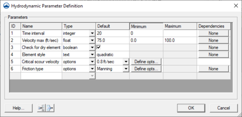
Dependencies are controlled on the child level when defining the model. To assign a dependency the parent and child parameters must exist and the parent must have its options defined. Dependencies are specified by clicking on the None button in the dependency column for the child parameter. Specify the parent desired to be used for this parameter, whether a global parameter or local (whatever level is currently being defined). Then check the boxes next to the parent parameters that will allow the child parameter to be visible. A child option may be visible for several parent options.
Whenever a parent object is invisible all children that are dependent upon the option are also invisible.
Generic 2D Mesh Arc Attributes Dialog
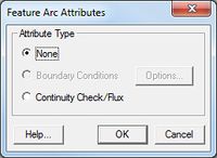
The Generic 2D Mesh Feature Arc Attributes dialog is used to set the attributes for feature arcs. Attributes that can be specified for each feature arc include:
- Arc Type
- None
- Boundary Conditions – Options button opens the Mesh Nodestring Boundary Conditions dialog.
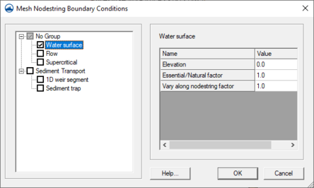
Mesh Nodestring Boundary Conditions Dialog
Generic 2D Mesh Boundary conditions are generally defined on feature arcs in the conceptual model or nodestrings on the 2D mesh. Boundary conditions constrain the water surface elevation and/or flow at the model boundary. The options available will be based on the current generic model in use and are defined in the Define Model dialog.
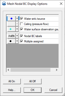
Generic 2D Nodal BC, Nodestring and Element Display Options
The properties of all Gen2DM (Generic 2D Mesh) node boundary conditions, nodestrings, and elements that SMS displays on the screen can be controlled here. This window is accessible only if the current 2D Mesh model is Generic (Mesh module’s Data | Switch Current Model… menu command). Open Display Options, turn on either Nodal BC, Nodestrings, or Elements and then select the corresponding Options button.
Display options are available for all boundary condition entities defined in the Gen2DM model definition. If no BC entities have been defined then a message will state that fact and display options will not be shown. Each defined BC entity has a checkbox to toggle the display of the item and an Attribute Options button to adjust style and color.
Below the list of BC entities is the display options for Inactive entities. Inactive entities are BC entities that are associated with an inactive parameter group (activation is controlled via the Gen2DM | Global Parameters menu item).
The BC entities can be displayed with labels beside them. Labels allows the user to adjust the label font, style, size, color and whether they are displayed. When Labels is checked for display, the auxiliary Show BC Values in labels is available. If checked, BC entities' values will be displayed following the entities’ description.
All on checks all BC entity display options.
All off unchecks all BC entity display options.
Overview
The designer/user can define whether the curves in their model are interpolated to the time step duration or not.
Saving the Model
The Generic Model Files are written automatically with the SMS project file or can be saved separately using the File | Save Mesh or File | Save As menu commands. See Generic Model Files for more information on the files used for the Generic Model run.
Related Topics
SMS – Surface-water Modeling System | ||
|---|---|---|
| Modules: | 1D Grid • Cartesian Grid • Curvilinear Grid • GIS • Map • Mesh • Particle • Quadtree • Raster • Scatter • UGrid |  |
| General Models: | 3D Structure • FVCOM • Generic • PTM | |
| Coastal Models: | ADCIRC • BOUSS-2D • CGWAVE • CMS-Flow • CMS-Wave • GenCade • STWAVE • WAM | |
| Riverine/Estuarine Models: | AdH • HEC-RAS • HYDRO AS-2D • RMA2 • RMA4 • SRH-2D • TUFLOW • TUFLOW FV | |
| Aquaveo • SMS Tutorials • SMS Workflows | ||

