GMS:Editing a 3D Mesh
Contents
Editing Nodes
3D mesh nodes can be:
- Moved – The coordinates of a 3D mesh node can be edited by selecting the node and dragging it to its new location or by typing the new coordinates in the Edit Window.
- Locked – Once a mesh has been created and edited as desired, the locations of all of the mesh nodes can be locked using the Lock All Nodes command. This is generally done to avoid inadvertent movement of the nodes while assigning boundary conditions and manipulating the view. Once the nodes can be unlocked by unselecting Lock All Nodes command.
- Deleted – 3D mesh nodes can be deleted by selecting the node and then the Delete command from the Edit menu or the Delete key.
- Renumbered – As a 3D mesh is constructed within GMS, the nodes and elements in the mesh are numbered arbitrarily. If any nodes or elements are deleted, gaps are created in the numbering sequence. Such gaps can be removed and an optimal numbering sequence can be achieved by selecting the Renumber command in the Mesh menu. Prior to selecting the Renumber command, the user should select a series of boundary faces of the 3D mesh. These faces represent the location where the numbering process is to begin. In most cases, it is best to select all of the faces on an entire side of the mesh. This can be accomplished using the Select Face tool with the Control key held down. The renumbering process renumbers the nodes and elements in a logical order that tends to minimize the node and element bandwidth (which leads to more efficient solutions with some finite element solvers). The process begins by ordering the nodes and faces of the selected group of faces. This is essentially a 2D renumbering process. The longitudinal and lateral directions of the region of selected faces are determined and the numbering proceeds by sweeping along rows oriented in the lateral direction while progressing from row to row in the longitudinal direction. Once the nodes and faces of the selected region are renumbered, the layer of elements adjacent to the faces are numbered in a similar sequence. This process is repeated by sweeping outward from the selected region, one layer of elements at a time, until the entire mesh is renumbered. The results of the renumbering process can be reviewed by turning on the display of node and/or element numbers in the Display Options dialog. The results can also be viewed by right-clicking on the 3D Mesh Data Folder in the Project Explorer and selecting the Properties command. The node and element bandwidths are listed in the dialog that comes up. If the objective of renumbering the mesh is minimizing the node and element bandwidths, the best results are generally achieved by selecting a side of the mesh corresponding to one of the two "ends" of the major or longitudinal axis of the mesh.
Refine Elements
3D mesh elements can be refined. Increasing the density of mesh elements can be accomplished by selecting a set of elements and selecting the Refine Elements command from the Mesh menu. This brings up the Refine Elements dialog.
Elements to Refine
The top portion of the dialog is used to specify which elements in the mesh are to be refined. If the Refine all 3D mesh elements option is selected, all elements in the mesh are refined regardless of which elements are selected. If the Refine selected 3D mesh elements option is selected, only the selected elements of the mesh are refined.
Even if the Refine selected 3D mesh elements option is selected, a few elements that were not selected must also be altered. This is due to the fact that the elements that were selected for refinement are refined, disjoint faces are created between the selected elements and the non-selected elements directly adjacent to the selected elements. To eliminate these disjoint faces, some transition elements are identified and refined. Transition elements are defined as any non selected element that shares at least one node with an element that is selected for refinement.
Refinement Method
There are three methods of refinement that can be used. The difference among the three methods is the shape of the resulting mesh elements. Each of the three methods is described below.
Vertical Column
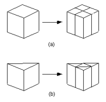
Vertical column refinement is used to split hexahedra and wedges in the X and Y directions only, as shown on the right.
Vertical column refinement was designed to be used with meshes created by extruding a 2D mesh through several layers. Meshes created in this manner are composed strictly of hexahedra and wedges and can be made by following the mesh extrusion procedure.
Depending upon the type and orientation of the elements in a 3D mesh, vertical column refinement may not be possible. When the Refine Elements options is selected from the Mesh menu, the entire mesh is checked to see if it can be refined using vertical column refinement. If vertical column refinement is not possible, the Vertical column refinement option is dimmed. In order for vertical column refinement to be possible, the following conditions must be met.
- If the entire mesh is to be refined, all elements in the mesh must be either hexahedra or wedges.
- If only a selected portion of the mesh is to be refined, all selected elements must be either hexahedra or wedges.
- All wedges to be refined must be oriented in space such that their top and bottom faces correspond to the triangular faces of the wedge.
- Both the top and bottom faces of each element to be refined must be on the boundary or adjacent to other elements that are also to be refined.
- All transition elements (i.e., elements not intended to be refined but share at least one node with an element that was selected for refinement) must also satisfy conditions 2 and 3 above.
All Elements To Tetrahedra
All element types to tets refinement is used to convert any of the four basic element types to tetrahedra. This option is especially useful since some finite element solvers require meshes to be composed strictly of tetrahedra.
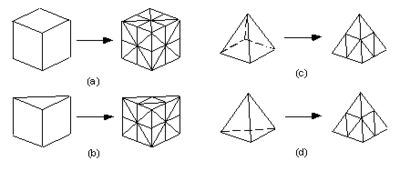
The Coarse refinement and Fine refinement options are used to specify the degree of refinement to be applied. If the Fine refinement option is selected, each tetrahedron is divided into eight smaller tetrahedra, each pyramid is divided into 16 smaller tetrahedra, each wedge is divided into 24 smaller tetrahedra, and each hexahedron is divided into 48 smaller tetrahedra. As with vertical column refinement, it is possible to refine either the entire mesh or selected portions of a mesh using the Fine refinement method.
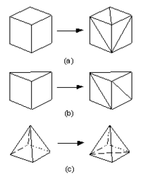
If the Coarse refinement option is selected, each pyramid is divided into two smaller tetrahedra, each wedge is divided into either three, or eight tetrahedra, and each hexahedra is divided into five, six, or twelve tetrahedra as shown below. Tetrahedra are not refined. Unlike the Fine refinement method, it is not possible to refine only a selected portion of a mesh when using the coarse method. The entire mesh gets refined.
Retain Element Types
Retain element types refinement is used to convert any of the four basic element types to smaller elements of the same type. For example, each hexahedra is divided into eight smaller hexahedra as shown below. Pyramids are the exception since they are divided into five smaller pyramids and four tetrahedra. It is possible to divide a pyramid into four smaller pyramids, but the resulting pyramids are of poor quality.
Like vertical column refinement, it is possible to refine only selected portions of a mesh when using Retain element types refinement. However, it is not always possible to retain element types in the transition elements. If the original mesh is composed of strictly tetrahedra, any selected region of the mesh can be refined without introducing elements other than tetrahedra. However, if the mesh contains any element type other than tetrahedra, pyramids and wedges will be introduced into the transition region.
| GMS – Groundwater Modeling System | ||
|---|---|---|
| Modules: | 2D Grid • 2D Mesh • 2D Scatter Point • 3D Grid • 3D Mesh • 3D Scatter Point • Boreholes • GIS • Map • Solid • TINs • UGrids | |
| Models: | FEFLOW • FEMWATER • HydroGeoSphere • MODAEM • MODFLOW • MODPATH • mod-PATH3DU • MT3DMS • MT3D-USGS • PEST • PHT3D • RT3D • SEAM3D • SEAWAT • SEEP2D • T-PROGS • ZONEBUDGET | |
| Aquaveo | ||


