GMS:Solid Properties
From XMS Wiki
(diff) ← Older revision | Latest revision (diff) | Newer revision → (diff)
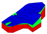
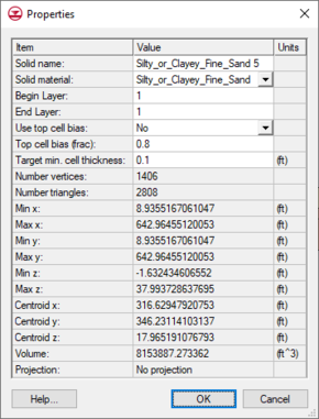
The Solid Properties dialog allows the user to edit/view attributes of the selected solid. This dialog can be accessed by selecting a solid from the Project Explorer, right-clicking to access the pop up menu, and selecting the Properties command. It can also be accessed by double-clicking on a solid in the graphics window, or by selecting a solid and then selecting the Properties command from the Edit menu.
The following items can be edited in the Properties dialog:
- Solid Name – Name of the solid.
- Solid Material – Material associated with the solid. The list will only show materials contained in the Materials dialog.
- Begin Layer – Beginning grid layer assigned to solid used with the Solids→MODFLOW procedure.
- End Layer – Ending grid layer assigned to solid used with the Solids→MODFLOW procedure.
- Use top cell bias– Option for using the top cell bias used with the Solids→MODFLOW procedure.
- Top cell bias – The percent to bias the thickness of the top cell with the Solids→MODFLOW procedure.
- Target min. cell thickness – Minimum cell thickness used with the Solids→MODFLOW procedure.
The following items are displayed as information about the solid and cannot be edited in the dialog:
- Number vertices – Total number of vertices used in the solid.
- Number triangles – Total number of traingle elements used in the solid.
- Max x – The maximum distance away from the origin on the x-axis.
- Min x – The minimum distance away from the origin on the x-axis.
- Max y – The maximum distance away from the origin on the y-axis.
- Min y – The minimum distance away from the origin on the y-axis.
- Max z – The maximum distance away from the origin on the z-axis.
- Min z – The minimum distance away from the origin on the z-axis.
- Centroid,x – The point on the x-axis that is at the center of the solid.
- Centroid,y – The point on the y-axis that is at the center of the solid.
- Centroid,z – The point on the z-axis that is at the center of the solid.
- Volume – The calculated volume of the solid.
- Projection – The projection coordinates the solid is using.
| GMS – Groundwater Modeling System | ||
|---|---|---|
| Modules: | 2D Grid • 2D Mesh • 2D Scatter Point • 3D Grid • 3D Mesh • 3D Scatter Point • Boreholes • GIS • Map • Solid • TINs • UGrids | |
| Models: | FEFLOW • FEMWATER • HydroGeoSphere • MODAEM • MODFLOW • MODPATH • mod-PATH3DU • MT3DMS • MT3D-USGS • PEST • PHT3D • RT3D • SEAM3D • SEAWAT • SEEP2D • T-PROGS • ZONEBUDGET | |
| Aquaveo | ||

