GMS:Creating and Editing UGrids
| This contains information about functionality available starting at GMS version 10.0. The content may not apply to other versions. |
| UGrid Module | |
|---|---|
 | |
| UGrid | |
| Creating and Editing | |
| Viewing Modes | |
| Converting to Other Data Types | |
| Exporting UGrids | |
| UGrid Interpolation | |
| More | |
| Display Options | |
| Tool Palette | |
| Cell Properties | |
| UGrid Commands | |
There are a number of ways to create UGrids.
Contents
Importing
UGrids can be imported from a VTK XML file by selecting the File|Open command or by dragging and dropping the file onto the GMS window. GMS recognizes the ".vtu" extension, which by convention is the extension used for a VTK XML file containing an unstructured grid.
Map -> UGrid
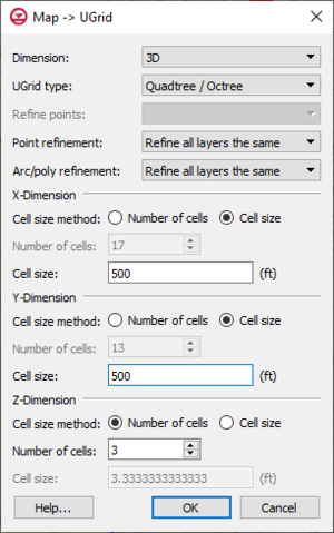
The Map -> UGrid command creates a UGrid from feature objects. It can be found in the Feature Objects menu and in some pop-up menus when right-clicking on items in the Project Explorer (Coverage, Grid Frame). The command opens the Create UGrid dialog.
Create UGrid Dialog
- Dimension - Specifies whether a 2D or 3D UGrid will be created.
- UGrid type
- Regular (not refined) - Creates a grid with rectangular cells that are not refined.
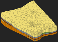
- Quad tree - Creates a grid with rectangular cells that is refined around refine points and arcs with cell sizes increasing in size with distance from the points and arcs.
- Voronoi - Creates a Voronoi grid with cells of various sizes and shapes to meet the Voronoi criteria. The active coverage must contain a polygon because it is first meshed with a triangular mesh and refined around points and arcs.
- Refine points - If the quad tree option is selected and refine points exist in multiple coverages, specifies which refine points to use.
- X, Y, Z number of cells
- If not using the Voronoi UGrid type, the size and number of cells in the X, Y and Z dimensions can be specified. For quad tree UGrids, the cell size represents the large, unrefined size because the small, refined size is determined by the refine points and arcs.
If a grid frame exists, it is used to determine the location of the grid.
Conversion From Other Data Types
The following data types can be converted to UGrids by right-clicking on the object in the Project Explorer and selecting the Convert To > UGrid command from the pop-up menu.
- TINs
- 2D Grids
- 3D Grids
- 2D Mesh
- 3D Mesh
- Polygons in a coverage (Map To > Polygons -> UGrid)
- Polygon shape files in the GIS Module
Horizons
The Horizons -> UGrid command (in the TINs and Boreholes menus) uses horizons to create a 3D UGrid.
| [hide]GMS – Groundwater Modeling System | ||
|---|---|---|
| Modules: | 2D Grid • 2D Mesh • 2D Scatter Point • 3D Grid • 3D Mesh • 3D Scatter Point • Boreholes • GIS • Map • Solid • TINs • UGrids | |
| Models: | FEFLOW • FEMWATER • HydroGeoSphere • MODAEM • MODFLOW • MODPATH • mod-PATH3DU • MT3DMS • MT3D-USGS • PEST • PHT3D • RT3D • SEAM3D • SEAWAT • SEEP2D • T-PROGS • ZONEBUDGET | |
| Aquaveo | ||
