SMS:ADCIRC Wind Coverage: Difference between revisions
| (32 intermediate revisions by 2 users not shown) | |||
| Line 1: | Line 1: | ||
The ADCIRC wind coverage represents a storm, such as a tropical depression or hurricane as an arc or series of arcs that follow the storm track and define the storm attributes at the nodes along the arc. This information is often available in a [http://www.nrlmry.navy.mil/atcf_web/docs/database/new/abrdeck.html "ATCF best track"] similar file. | The ADCIRC wind coverage represents a storm, such as a tropical depression or hurricane, as an arc or series of arcs that follow the storm track and define the storm attributes at the nodes along the arc. This information is often available in a [http://www.nrlmry.navy.mil/atcf_web/docs/database/new/abrdeck.html "ATCF best track"] similar file. It is called a "similar" file, because the ADCIRC development group have modified the format slightly for each type of application. | ||
Data in the ATCF best track format for historical storms are available from various locations including [http://tropicalatlantic.com/modelsOLD/ tropicalatlatic.com/modelsOLD]. | Data in the ATCF best track format for historical storms are available from various locations including [http://tropicalatlantic.com/modelsOLD/ tropicalatlatic.com/modelsOLD]. | ||
SMS can import data in this format or extract data from the HURDAT database and convert it to this format to associate it with an ADCIRC simulation. The data can be utilized for three of the | SMS can import data in this format or extract data from the HURDAT database and convert it to this format to associate it with an ADCIRC simulation. The data can be utilized for three of the Node Wind Stress (NWS) types supported by ADCIRC including: NWS = 8 (symmetric vortex model), NWS = 12 (OWI PBL wind format), and NWS = 19 (asymmetric vortex model). Depending on the selected option for NWS, SMS will export the data as a file named fort.22 for the ADCIRC simulation in formats compatible with either NWS = 8 or NWS = 19, or as a ".trop" file for use by PBL. | ||
Various model checks have been implemented to help | Various model checks have been implemented to help catch mistakes and avoid crossing ADCIRC's limitations. | ||
To create a wind coverage, simply open one of these file into SMS. Alternatively, create a new coverage and select the coverage type ''Models'' | '''Wind''' or | To create a wind coverage, simply open one of these file into SMS. Alternatively, create a new coverage and select the coverage type ''Models'' | '''Wind''' or convert an existing coverage by right-clicking it and selecting ''Type'' | ''Models'' | '''Wind'''. | ||
== | ==Storm Attributes== | ||
To access the '' | [[File:StormAttributes.png|thumb|235 px|The ''Storm Attributes'' dialog]] | ||
* Wind Model: Choose between symmetric and asymmetric definition of the storm. The wind model will determine which fields are displayed and which are hidden (by default) in the node attributes dialog. | To access the ''Storm Attributes'', right-click on the coverage and select '''Properties...'''. The ''Storm Attributes'' dialog contains several separate fields that apply to the entire hurricane, such as whether it is symmetric or asymmetric. The storm's symmetry in particular is important to set before editing node properties because it affects which fields are shown by default and regarded as required. | ||
* ''Wind Model'': Choose between symmetric and asymmetric definition of the storm. The wind model will determine which fields are displayed and which are hidden (by default) in the node attributes dialog. | |||
* | ** ''Holland Symmetrical'': The basic and default choice, and assumes a simple storm definition will suffice. | ||
* | ** ''Holland Asymmetrical'': Gives more options for defining the storm's shape and orientation. | ||
* | ** ''Planetary Boundary Layer (PBL)'': Activates an '''Options''' button that will bring up the ''PBL Model Control'' dialog. Model isn't currently available. | ||
*''Wind Attributes'' | |||
* Basin | ** ''Basin'': Defines a world region where the storm is taking place. | ||
* Annual cyclone number: Does not affect calculations, but is valuable for book keeping. | ** ''Subregion'': Defines a world region where the storm is taking place. | ||
** ''Annual cyclone number'': Does not affect calculations, but is valuable for book keeping. | |||
==Building a Storm Path== | ==Building a Storm Path== | ||
The storm path should be a single continuous line with no breaks or branches. Simply clicking out an arc is sufficient—vertices will be converted to nodes once | The storm path should be a single continuous line with no breaks or branches. Simply clicking out an arc is sufficient—vertices will be converted to nodes once the ''Node Attributes'' dialog is entered. | ||
Do: | Do: | ||
* Operate in Geographic Coordinates | * Operate in Geographic Coordinates | ||
* Make a single path with no breaks | * Make a single path with no breaks | ||
* Create the number of vertices/nodes that there is data for ( | * Create the number of vertices/nodes that there is data for (adjust their positions manually with the nodes/vertices selected or can set their positions within the ''Node Attributes'' dialog) | ||
Don't: | Don't: | ||
* Create multiple paths in the same coverage | * Create multiple paths in the same coverage | ||
* Split the path in multiple directions | * Split the path in multiple directions | ||
* Create loops with the path | * Create loops with the path | ||
<gallery widths="300px" heights="240px" perrow="5"> | |||
File:Stormpath1.jpg|Good example of a storm path. | |||
File:Stormpath2.jpg|A good path can cross itself as long as it does not connect at the intersection. | |||
File:Stormpath3.jpg|Path should not branch as in this picture. | |||
File:Stormpath4.jpg|Path should never loop as shown. | |||
File:Stormpath5.jpg|Only one path can exist. Multiple paths as shown are not allowed. | |||
File:Stormpath6.jpg|Different portions of the path cannot converge on each other. The arrows for each section of the path should all point in the same direction for the whole length of the path. | |||
</gallery> | |||
[[Category:Gallery]] | |||
===Notes=== | ===Notes=== | ||
| Line 48: | Line 45: | ||
==Node Attributes== | ==Node Attributes== | ||
[[File:Storm Track Node Attributes. | [[File:Storm Track Node Attributes.png|thumb|400 px|''Storm Track Node Attributes'' dialog]] | ||
Once | Once a storm path has been built, define the storm's attributes at each node of the path. Enter the ''Node Attributes'' dialog by selecting the '''Select Feature Point''' tool and double-clicking anywhere in the coverage. This opens the ''Storm Track Node Attributes'' dialog. Whenever this dialog opens, all vertices in the storm path are converted to nodes automatically. | ||
A second way to open the ''Node Attributes'' dialog is to use the '''Select Feature Point''' tool to select one or more nodes on the path. Then right-click and select '''Node Attributes...'''. This will highlight those nodes in the dialog. | A second way to open the ''Node Attributes'' dialog is to use the '''Select Feature Point''' tool to select one or more nodes on the path. Then right-click and select '''Node Attributes...'''. This will highlight those nodes in the dialog. | ||
| Line 55: | Line 52: | ||
Fields colored blue and displayed by default are those that are required for the Wind Model (symmetric or asymmetric) selected in the ''Coverage Attributes'' dialog. The '''Show all'''/'''Show only required''' button can be used to show all the fields available, even those not used by ADCIRC or for the selected wind model. These are useful for book keeping and completeness, even though they typically do not affect calculations. | Fields colored blue and displayed by default are those that are required for the Wind Model (symmetric or asymmetric) selected in the ''Coverage Attributes'' dialog. The '''Show all'''/'''Show only required''' button can be used to show all the fields available, even those not used by ADCIRC or for the selected wind model. These are useful for book keeping and completeness, even though they typically do not affect calculations. | ||
The Storm start time sets the starting time for the first node in the storm's path. Each node then defines an offset from this starting time in hours (see below). Year, month, day and hour are important, while minutes and seconds should be left at 0. | The ''Storm start time'' sets the starting time for the first node in the storm's path. Each node then defines an offset from this starting time in hours (see below). Year, month, day and hour are important, while minutes and seconds should be left at 0. | ||
The fields in the spreadsheet more or less correspond directly to a field in the fort.22 file | The fields in the spreadsheet more or less correspond directly to a field in the fort.22 file: | ||
* Lat and Lon: These define the latitude and longitude of the given node, in tenths of degrees (900 = 90 degrees). | * ''Lat and Lon'': These define the latitude and longitude of the given node, in tenths of degrees (900 = 90 degrees). Edit these values directly from the dialog or select the nodes with the '''Select Feature Point''' tool and edit their X and Y that way. In this dialog, values are always positive and N/S/E/W determines quadrant, whereas the main SMS interface uses negative numbers for South and East. | ||
* TechNum/Minutes (TECHNUM/MM) | * ''TechNum/Minutes (TECHNUM/MM)'' | ||
* Technique (TECH): ADCIRC recommends that this be set to ASYM when dealing with asymmetric storms | * ''Technique (TECH)'': ADCIRC recommends that this be set to ASYM when dealing with asymmetric storms | ||
* Time offset (YYYYMMDDHH and TAU): This field combined with the Storm start time above the spreadsheet determine the YYYYMMDDHH and TAU fields in the fort.22. This field is the offset (in hours) from the storm start time. | * ''Time offset (YYYYMMDDHH and TAU)'': This field combined with the Storm start time above the spreadsheet determine the YYYYMMDDHH and TAU fields in the fort.22. This field is the offset (in hours) from the storm start time. | ||
* Max sust wind spd (VMAX) | * ''Max sust wind spd (VMAX)'' | ||
* Minimum sea lvl pressure (MSLP) | * ''Minimum sea lvl pressure (MSLP)'': This is another reflection of the storm strength. | ||
* Lvl of tc development (TY) | * ''Lvl of tc development (TY)'' | ||
* Wind radius code (WINDCODE): ADCIRC requires that this be full circle for symmetric, and northeast quadrant for asymmetric. This is fairly restrictive, but SMS can convert many of the other options to northeast quadrant automatically. A model check will warn | * ''Wind radius code (WINDCODE)'': ADCIRC requires that this be full circle for symmetric, and northeast quadrant for asymmetric. This is fairly restrictive, but SMS can convert many of the other options to northeast quadrant automatically. A model check will warn if some of the selections cannot be converted without losing data. | ||
* Wind Intensity (RAD, RAD1-4): Each node can store wind intensity and radii for the storm shape at 34, 50, 64 and 100 kts. | * ''Wind Intensity (RAD, RAD1-4)'': Each node can store wind intensity and radii for the storm shape at 34, 50, 64 and 100 kts. | ||
* Pressure of last closed isobar (RADP) | * ''Pressure of last closed isobar (RADP)'' | ||
* Radius of last closed isobar (RRP) | * ''Radius of last closed isobar (RRP)'': This defines the size of the storm's significant influence. | ||
* Radius of max winds (MRD) | * ''Radius of max winds (MRD)'': This defines the size of the central portion of the storm. | ||
* Gusts (GUSTS) | * ''Gusts (GUSTS)'' | ||
* Eye diameter (EYE) | * ''Eye diameter (EYE)'' | ||
* Max seas (MAXSEAS) | * ''Max seas (MAXSEAS)'' | ||
* Forcaster's initials (INITIALS) | * ''Forcaster's initials (INITIALS)'' | ||
* Storm direction (DIR) | * ''Storm direction (DIR)'' | ||
* Storm speed (SPEED) | * ''Storm speed (SPEED)'' | ||
* Storm name (STORMNAME) | * ''Storm name (STORMNAME)'' | ||
* System depth (DEPTH) | * ''System depth (DEPTH)'' | ||
* Wave height for radii (SEAS) | * ''Wave height for radii (SEAS)'' | ||
* Seas radius code (SEASCODE) | * ''Seas radius code (SEASCODE)'' | ||
* Wave height radius 1-4 (SEAS1-4) | * ''Wave height radius 1-4 (SEAS1-4)'' | ||
==Linking the Coverage to the ADCIRC Project== | ==Linking the Coverage to the ADCIRC Project== | ||
After defining the storm path and all its data, it's time to link the project into ADCIRC. To do this, select the ADCIRC mesh and go to ''ADCIRC'' | '''Model Control'''. | |||
Choose the ''Wind'' tab. Select either Dynamic Holland Model (NWS=8) or Asymmetric vortex, Holland gradient wind model (NWS=9). In the ''Wind File Options'' section, click '''Choose coverage...''' to select the coverage and link it in. The '''Options''' button will now open the ''Coverage Attributes'' dialog | Choose the ''Wind'' tab. Select either Dynamic Holland Model (NWS=8) or Asymmetric vortex, Holland gradient wind model (NWS=9). In the ''Wind File Options'' section, click '''Choose coverage...''' to select the coverage and link it in. The '''Options''' button will now open the ''Coverage Attributes'' dialog which allows editing it quickly from this dialog. | ||
In the ''Timing'' tab be sure to set up the simulation start time and how long it runs. The wind coverage's time span should have the same start time and duration, or be longer so that it encompasses the simulation time span. | In the ''Timing'' tab be sure to set up the simulation start time and how long it runs. The wind coverage's time span should have the same start time and duration, or be longer so that it encompasses the simulation time span. | ||
Also set up any other ADCIRC settings as needed. When finished, click '''OK''', then go to ''File'' | '''Save ADCIRC''', then ''ADCIRC'' | '''Run ADCIRC'''. The model check will alert | Also set up any other ADCIRC settings as needed. When finished, click '''OK''', then go to ''File'' | '''Save ADCIRC''', then ''ADCIRC'' | '''Run ADCIRC'''. The model check will alert to any potential problems before ADCIRC runs. | ||
==Related Topics== | |||
* [[SMS:ADCIRC|ADCIRC]] | |||
{{Template:Navbox SMS}} | {{Template:Navbox SMS}} | ||
[[Category: | [[Category:ADCIRC Dialogs|Wind]] | ||
[[Category:ADCIRC| | [[Category:ADCIRC|Wind]] | ||
[[Category:SMS Coverages| | [[Category:SMS Coverages|ADCIRC]] | ||
[[Category:SMS Map| | [[Category:SMS Map|ADCIRC]] | ||
[[Category:External Links]] | |||
Latest revision as of 15:47, 28 April 2023
The ADCIRC wind coverage represents a storm, such as a tropical depression or hurricane, as an arc or series of arcs that follow the storm track and define the storm attributes at the nodes along the arc. This information is often available in a "ATCF best track" similar file. It is called a "similar" file, because the ADCIRC development group have modified the format slightly for each type of application.
Data in the ATCF best track format for historical storms are available from various locations including tropicalatlatic.com/modelsOLD.
SMS can import data in this format or extract data from the HURDAT database and convert it to this format to associate it with an ADCIRC simulation. The data can be utilized for three of the Node Wind Stress (NWS) types supported by ADCIRC including: NWS = 8 (symmetric vortex model), NWS = 12 (OWI PBL wind format), and NWS = 19 (asymmetric vortex model). Depending on the selected option for NWS, SMS will export the data as a file named fort.22 for the ADCIRC simulation in formats compatible with either NWS = 8 or NWS = 19, or as a ".trop" file for use by PBL.
Various model checks have been implemented to help catch mistakes and avoid crossing ADCIRC's limitations.
To create a wind coverage, simply open one of these file into SMS. Alternatively, create a new coverage and select the coverage type Models | Wind or convert an existing coverage by right-clicking it and selecting Type | Models | Wind.
Storm Attributes

To access the Storm Attributes, right-click on the coverage and select Properties.... The Storm Attributes dialog contains several separate fields that apply to the entire hurricane, such as whether it is symmetric or asymmetric. The storm's symmetry in particular is important to set before editing node properties because it affects which fields are shown by default and regarded as required.
- Wind Model: Choose between symmetric and asymmetric definition of the storm. The wind model will determine which fields are displayed and which are hidden (by default) in the node attributes dialog.
- Holland Symmetrical: The basic and default choice, and assumes a simple storm definition will suffice.
- Holland Asymmetrical: Gives more options for defining the storm's shape and orientation.
- Planetary Boundary Layer (PBL): Activates an Options button that will bring up the PBL Model Control dialog. Model isn't currently available.
- Wind Attributes
- Basin: Defines a world region where the storm is taking place.
- Subregion: Defines a world region where the storm is taking place.
- Annual cyclone number: Does not affect calculations, but is valuable for book keeping.
Building a Storm Path
The storm path should be a single continuous line with no breaks or branches. Simply clicking out an arc is sufficient—vertices will be converted to nodes once the Node Attributes dialog is entered. Do:
- Operate in Geographic Coordinates
- Make a single path with no breaks
- Create the number of vertices/nodes that there is data for (adjust their positions manually with the nodes/vertices selected or can set their positions within the Node Attributes dialog)
Don't:
- Create multiple paths in the same coverage
- Split the path in multiple directions
- Create loops with the path
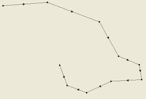
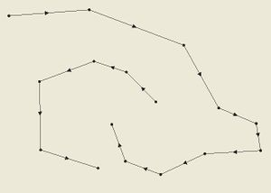
Good example of a storm path.
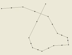
A good path can cross itself as long as it does not connect at the intersection.
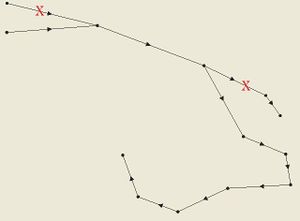
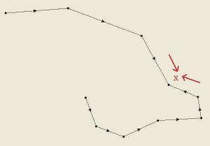
Path should not branch as in this picture.
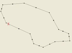
Path should never loop as shown.
Only one path can exist. Multiple paths as shown are not allowed.
Different portions of the path cannot converge on each other. The arrows for each section of the path should all point in the same direction for the whole length of the path.


Notes
Consequently, the storm path and nodes information may be obtained in a hurdat file obtained on the NOAA website. Access website and save the Easy to Read version of the file. Extension for file must be saved as hurdat in order to open in SMS.
Node Attributes

Once a storm path has been built, define the storm's attributes at each node of the path. Enter the Node Attributes dialog by selecting the Select Feature Point tool and double-clicking anywhere in the coverage. This opens the Storm Track Node Attributes dialog. Whenever this dialog opens, all vertices in the storm path are converted to nodes automatically.
A second way to open the Node Attributes dialog is to use the Select Feature Point tool to select one or more nodes on the path. Then right-click and select Node Attributes.... This will highlight those nodes in the dialog.
Fields colored blue and displayed by default are those that are required for the Wind Model (symmetric or asymmetric) selected in the Coverage Attributes dialog. The Show all/Show only required button can be used to show all the fields available, even those not used by ADCIRC or for the selected wind model. These are useful for book keeping and completeness, even though they typically do not affect calculations.
The Storm start time sets the starting time for the first node in the storm's path. Each node then defines an offset from this starting time in hours (see below). Year, month, day and hour are important, while minutes and seconds should be left at 0.
The fields in the spreadsheet more or less correspond directly to a field in the fort.22 file:
- Lat and Lon: These define the latitude and longitude of the given node, in tenths of degrees (900 = 90 degrees). Edit these values directly from the dialog or select the nodes with the Select Feature Point tool and edit their X and Y that way. In this dialog, values are always positive and N/S/E/W determines quadrant, whereas the main SMS interface uses negative numbers for South and East.
- TechNum/Minutes (TECHNUM/MM)
- Technique (TECH): ADCIRC recommends that this be set to ASYM when dealing with asymmetric storms
- Time offset (YYYYMMDDHH and TAU): This field combined with the Storm start time above the spreadsheet determine the YYYYMMDDHH and TAU fields in the fort.22. This field is the offset (in hours) from the storm start time.
- Max sust wind spd (VMAX)
- Minimum sea lvl pressure (MSLP): This is another reflection of the storm strength.
- Lvl of tc development (TY)
- Wind radius code (WINDCODE): ADCIRC requires that this be full circle for symmetric, and northeast quadrant for asymmetric. This is fairly restrictive, but SMS can convert many of the other options to northeast quadrant automatically. A model check will warn if some of the selections cannot be converted without losing data.
- Wind Intensity (RAD, RAD1-4): Each node can store wind intensity and radii for the storm shape at 34, 50, 64 and 100 kts.
- Pressure of last closed isobar (RADP)
- Radius of last closed isobar (RRP): This defines the size of the storm's significant influence.
- Radius of max winds (MRD): This defines the size of the central portion of the storm.
- Gusts (GUSTS)
- Eye diameter (EYE)
- Max seas (MAXSEAS)
- Forcaster's initials (INITIALS)
- Storm direction (DIR)
- Storm speed (SPEED)
- Storm name (STORMNAME)
- System depth (DEPTH)
- Wave height for radii (SEAS)
- Seas radius code (SEASCODE)
- Wave height radius 1-4 (SEAS1-4)
Linking the Coverage to the ADCIRC Project
After defining the storm path and all its data, it's time to link the project into ADCIRC. To do this, select the ADCIRC mesh and go to ADCIRC | Model Control. Choose the Wind tab. Select either Dynamic Holland Model (NWS=8) or Asymmetric vortex, Holland gradient wind model (NWS=9). In the Wind File Options section, click Choose coverage... to select the coverage and link it in. The Options button will now open the Coverage Attributes dialog which allows editing it quickly from this dialog.
In the Timing tab be sure to set up the simulation start time and how long it runs. The wind coverage's time span should have the same start time and duration, or be longer so that it encompasses the simulation time span.
Also set up any other ADCIRC settings as needed. When finished, click OK, then go to File | Save ADCIRC, then ADCIRC | Run ADCIRC. The model check will alert to any potential problems before ADCIRC runs.
Related Topics
SMS – Surface-water Modeling System | ||
|---|---|---|
| Modules: | 1D Grid • Cartesian Grid • Curvilinear Grid • GIS • Map • Mesh • Particle • Quadtree • Raster • Scatter • UGrid |  |
| General Models: | 3D Structure • FVCOM • Generic • PTM | |
| Coastal Models: | ADCIRC • BOUSS-2D • CGWAVE • CMS-Flow • CMS-Wave • GenCade • STWAVE • WAM | |
| Riverine/Estuarine Models: | AdH • HEC-RAS • HYDRO AS-2D • RMA2 • RMA4 • SRH-2D • TUFLOW • TUFLOW FV | |
| Aquaveo • SMS Tutorials • SMS Workflows | ||