Coverages Tools
This article describes tools from the SMS toolbox designed to perform specialized modifications to to feature objects inside coverages.
Coverages Tools
Centroids from Polygons
Clip
See Clip
Contours from Raster
Contours from Single Raster Value
See Contours from Single Raster Value
Features from Raster
The Features from Raster tool derives features such as streams and roadway embankments from an elevation raster.
Input Parameters
- Input raster – Select the input elevation raster.
- Feature type – Select the feature type to generate.
- "Stream" – This option generates stream lines given the threshold area for stream generation.
- "Ridge" – This option generates ridge lines for the inverted raster given the threshold area for ridge generation.
- Threshold area – The threshold area to use for stream or ridge generation.
- Pre-processing engine – Which pre-processing engine to use.
- "rho8" – Computes flow directions and accumulations using the Rho8 algorithm.
- "Whitebox full workflow" – Computes flow directions and accumulations using the Whitebox tool full workflow algorithm that uses a standard D8 method for computing flow directions.
Output Parameters
- Output coverage – Defines the name of the tool-generated output coverage
- Breached, Flow direction, and Flow accumulation rasters are also generated from this tool. The names of these are currently hardwired to the original raster names ending in _breached, _flowdir, and _flowaccum respectively. An additional extension is added to the end of the raster name based on the pre-processing engine used.
Current Location in toolbox
Coverages/Features from Raster
Polygon from Raster Bounds
The Polygon from Raster Bounds tool creates a new coverage with polygons bounding all of the active regions of the raster. Any inactive regions that fall within an interior polygon will be deleted automatically.
Inactive regions of a raster are determined by the NODATA value of the raster.


Input Parameters
- Input raster – The raster for which the active boundary polygon will be created.
Output Parameters
- Output coverage – The new coverage to be created, containing the boundary polygon for the active region of the input raster.
Current Location in Toolbox
Coverages/Polygon from Raster Bounds
Polygons from Arcs
The Polygons from Arcs tool converts all arcs in a coverage to polygons based on specified parameters.
This tool is designed to simplify the creation of linear polygons to represent features such as channels or embankments. The feature extraction operations create stream or ridge networks. These features can be used to position cells/elements in a mesh/UGrid to honor these features. However, it is often useful to represent such linear features as Patch polygons to allow or anisotropic cells—elongated in the direction of the feature.
Each arc in the input polygon will be converted to a polygon. The following applies during the creating process:
- The polygon for isolated lines/arcs will consist of offset lines in both directions from the arc. The ends of the polygon will be perpendicular to the end segment of the arc.
- If two arcs are connected (end to end), the orientation of the two polygons will be averaged so that the polygons share and "end".
- If three arcs/lines join at a node, the two that have the most similar direction will be maintained as a continuous feature. The third will be trimmed back to not encroach on the polygons of the other two. If more than three arcs/lines join at a single location, the two arcs with the most similar direction will define the preserved direction. All other arcs will be trimmed back to not encroach.
- If a single arc closes in a loop, the resulting polygon closes on itself. This polygon will not function as a patch in SMS. This workflow is not recommended.
- The tool performs a check to determine if the polygons from two unconnected overlap/intersect each other. This is reported in the progress dialog.
Input Parameters
- Input coverage – This can be any map coverage in the project. The arcs in the coverage will be used to guide polygon creation.
- Average element/cell width – This defines the average width of the segments projecting perpendicular from the arc. The units (foot/meter) correspond to the display projection of SMS.
- Number of elements/cells (must be even) – This defines the number of segments projecting in each direction from the centerline. Because it is projected in both directions, it must be even.
- Bias (0.01-100.0) – This provides control of the relative length of the segments across the feature. In this case, it is actually a double bias because both sides of the feature are biased from the outer edges to the center. Therefore, a bias less than 1.0 results in segments that are shorter at the center. A bias greater than 1.0 results in segments that are longer at the center. Specify a small bias to improve representation of the channel bottom or embankment crest and a larger bias to increase resolution (representation) or the outer edge (shoulder or toes) of the feature. See images below for examples.
Output Parameters
- Output coverage – Specify the name of the coverage to be created that will contain the generated polygons. The intent of this coverage is to be incorporate into a mesh generation coverage for the domain. The resulting coverage will have the Area Property coverage and will need to be changed to the desired coverage type.
Current Location in Toolbox
Coverages/Polygons from Arcs
Examples
Example 1 – 2 segment wide channel

In this case the average element/cell width was set to "w". Since each half has one cell, both segments are "w". The total width is therefore "2.0 w". Since there are only 2 segments, the bias value has no impact in this case.
Example 2 – 4 segment wide channel with bias greater than 1.0

In this case with an average segment length (element/cell width) of "w" the total width is "4.0 w". Since the bias is 2.0, the center segments are twice as long as the outer segments.
Example 3 – 4 segment wide channel with bias less than 1.0

In this case with an average segment length (element/cell width) of "w" the total width is "4.0 w". Since the bias is 0.5, the center segments are half as long as the outer segments.
Example 4 – 6 segment wide channel with bias greater than 1.0

In this case with an average segment length (element/cell width) of "w" the total width is "6.0 w". Since the bias is 2.0, the center segments are twice as long as the outer segments.
Example 5 – End to End Arcs to Polygons

The offset at the junction of the two arcs is adjusted to be perpendicular to the average of the two arcs. The two polygons would create a continuous channel.
Example 6 – Tributary Arcs to Polygons

At the junction of more than two arcs, the two that are closest to linear are assumed to be the main channel and the polygons for those two are treated just like example 5. The other arcs connected to this junction are treated as a tributary. The arc is still converted to a polygon, but any vertices on the arc within two widths of the junction are ignored to allow room for a transition between the channels to occur. (Note: it is anticipated that in the future this will be modified to allow for T or Y type merging of the polygons for junctions of three arcs.)
Example 7 – Parallel Arcs that Result in Overlapping Channel Polygons

If two arcs being converted to polygons result in overlapping polygons, the tool reports this issue using one of the overlapping arc indices. It is the responsibility of the modeler to adjust the arcs and convert to non-overlapping polygons, or clean up the overlapping polygons manually.

Related Tools
Polygons from Index Raster
The Polygons from Index Raster tool converts index (normally integer-valued) raster data to polygons.


Input Parameters
- Input index raster – Select the input index raster.
Output Parameters
- Index polygon coverage – The output polygon coverage created from the index raster.
Current Location in toolbox
Coverages/Polygons from Index Raster
Polygon from Raster Nodata
The Polygon from Raster Nodata tool creates a new coverage with polygons bounding all of the active regions of the raster including inactive regions that fall within an interior polygon.
Inactive regions of a raster are determined by the NODATA value of the raster.


Input Parameters
- Input raster – The raster for which the active boundary polygon will be created.
- Number of cells required to make a polygon – The number of cells required to make a polygon. Any interior areas that contain less raster cells than this number will not be enveloped with a polygon.
Output Parameters
- Output coverage – The new coverage to be created, containing the boundary polygon for the active region of the input raster.
Current Location in Toolbox
Coverages/Polygon from Raster Nodata
Polygons from UGrid Boundary
The Polygons from UGrid Boundary tool converts the outer boundary of a UGrid to polygons in a new coverage. This tool only functions on UGrids with 2D Cells.
Input parameters
- Input grid – The UGrid (or 2D mesh/scatter) whose boundary will be converted to arcs in a coverage.
Output parameters
- Output coverage name – Name of the coverage created by the tool. If this is left blank then the name of the coverage will be set to the name of the input grid.
Current location in Toolbox
Coverages/Polygons from UGrid Boundary
Example

Example input UGrid
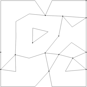
Example output coverage


Snap Outlet Points to Streams
See Snap Outlet Points to Streams
Streams from Raster
Trim Coverage
The Trim Coverage tool is used to remove features in a coverage that are not desired based on their location. The tool trims all arcs in a selected coverage to the polygons of another selected coverage. Arcs can be trimmed to preserve the portions of the arcs inside or outside of the trimming polygons. The user also specifies a buffer distance to allow the trimming to not retain the intersection points
A specific applications of this tool would be to trim extracted features that are outside of the desired simulation domain. Another application would be to clear out feature arcs that are inside the extents of a predominant feature such as a main river channel.
The tool allows for trimming data to features that are either inside or outside of the desired polygons.
For "large" polygons (> 2500 points), the polygon point locations will be smoothed prior to computing the polygon buffer. This is done because there are cases where the buffer distance combined with the polygon segment orientations causes the buffer operation to be very slow. Smoothing the locations prevents this slowdown.
Input Parameters
- Input coverage containing arcs to be trimmed – Select a coverage from the dropdown list. The arcs on this coverage will be trimmed.
- Input coverage containing polygons to trim by – Select a coverage from the dropdown list. The arcs on this coverage will be used to trim the arcs on the target coverage.
- Trimming option – Trim to inside or Trim to outside.
- "Trim to inside" – Trim to inside only keeps portions of the arcs that are inside of the polygons. .
- "Trim to outside" – Trim to outside only keeps the arc portions that are outside of the polygons.
- Trimming buffer distance – Enter a value that defines an offset (either inside if trimming to inside, or outside if trimming to outside) of the trimming polygons. This can be used to keep the results from being too close to the trimming polygon(s).
Output Parameters
- Output coverage – specify the name of the coverage to be created (representing the trimmed arcs).
Current Location in Toolbox
Coverages/Trim Coverage
Related Tools
Watershed from Raster
The Watershed from Raster tool derives a watershed and its streams locations from an elevation raster and one or more outlet locations. This is actually a workflow that invokes several tools sequentially. The tools that are invoked include:
- Breach Depressions Least Cost
- Rho8 Flow Directions or D8 Flow Directions (Depending on the selected pre-processing engine)
- D8 Flow Accumulation
- Extract Streams
- Streams from Raster
- Snap Outlet Points to Streams
- Watershed Delineation
- Polygons from Index Raster
After these tools the following operations are performed:
- The basin boundary is smoothed
- The streams are cleaned and trimmed to the basin
Input Parameters
- Input raster – Select the input elevation raster.
- Outlet coverage – Select a coverage containing one or more outlet points close to the watershed and/or sub-basin outlet(s). These points do not need to be directly on a flow accumulation cell since the algorithm searches for the closest stream to the defined outlet locations.
- Threshold area – The threshold area to use for stream or ridge generation.
- Pre-processing engine – Select which pre-processing engine to use.
- "rho8" – Computes flow directions and accumulations using the Rho8 algorithm.
- "Whitebox full workflow" – Computes flow directions and accumulations using the Whitebox tool full workflow algorithm that uses a standard D8 method for computing flow directions.
Output Parameters
- Output coverage – Defines the name of the tool-generated output coverage containing the watershed boundary.
- Coverages containing the modified outlet location(s) and the stream locations are also created with this tool. The name of these coverages are currently hardwired to the original raster names with an extension at the end based on the options selected in the tool.
- Breached, Flow direction, and Flow accumulation rasters are also generated from this tool. The names of these are currently hardwired to the original raster names ending in _breached, _flowdir, and _flowaccum respectively. An additional extension is added to the end of the raster name based on the pre-processing engine used.
Current Location in toolbox
Coverages/Watershed from Raster
| [hide] SMS – Surface-water Modeling System | ||
|---|---|---|
| Modules: | 1D Grid • Cartesian Grid • Curvilinear Grid • GIS • Map • Mesh • Particle • Quadtree • Raster • Scatter • UGrid |  |
| General Models: | 3D Structure • FVCOM • Generic • PTM | |
| Coastal Models: | ADCIRC • BOUSS-2D • CGWAVE • CMS-Flow • CMS-Wave • GenCade • STWAVE • WAM | |
| Riverine/Estuarine Models: | AdH • HEC-RAS • HYDRO AS-2D • RMA2 • RMA4 • SRH-2D • TUFLOW • TUFLOW FV | |
| Aquaveo • SMS Tutorials • SMS Workflows | ||