GMS:3D Mesh Module
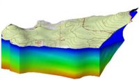
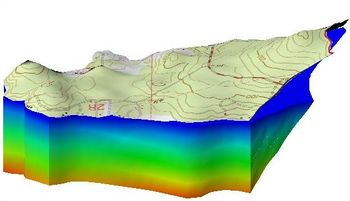
The 3D Mesh module is used to create and edit 3D finite element meshes. A 3D mesh consists of nodes, elements, and faces. A 3D mesh can be created from a 2D mesh, a 3D grid, 3D scatter points, or by using the automated meshing tools in GMS.
Once a mesh is constructed, the FEMWATER interface can be used to assign boundary conditions and analysis parameters and perform a FEMWATER analysis.
The module includes tools for manipulating 3D meshes as well as its own menu commands and display options. 3D meshes can be converted into 2D meshes, 3D scatter points, Ugrids, or solids. The module also can classify material zones and use isosurface rendering.
Currently, only one 3D mesh can exist in a GMS project. GMS is able to work with large or complicated 3D finite element meshes.
The 3D Mesh module can be added to a paid edition of GMS.
3D Element Types
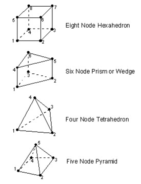
Four types of 3D elements are supported by GMS: eight node hexahedra, six node prisms or wedges, four node tetrahedra, and five node pyramids. Hexahedra and wedges are created by projecting a 2D mesh. Tetrahedral elements are constructed with the Tessellate command or they can be created elsewhere and imported into GMS.
| GMS – Groundwater Modeling System | ||
|---|---|---|
| Modules: | 2D Grid • 2D Mesh • 2D Scatter Point • 3D Grid • 3D Mesh • 3D Scatter Point • Boreholes • GIS • Map • Solid • TINs • UGrids | |
| Models: | FEFLOW • FEMWATER • HydroGeoSphere • MODAEM • MODFLOW • MODPATH • mod-PATH3DU • MT3DMS • MT3D-USGS • PEST • PHT3D • RT3D • SEAM3D • SEAWAT • SEEP2D • T-PROGS • ZONEBUDGET | |
| Aquaveo | ||


