SMS:Bridge-Piers Coverage
| This contains information about features no longer in use for the current release of SMS. The content may not apply to current versions. |
The coverage needs to be set to the Bridge-Piers type. In a Bridge-Piers coverage there are several tools available. These tools are found by right-clicking a Bridge-Piers coverage in the Project Explorer and going to the Tools submenu.
Generate Bridge Mesh
This will bring up the Generate Mesh dialog, where the parameters of the bridge to be meshed are defined.
- See Create Bridge Footprint Tool for details and explanations.
Insert Bridge into Mesh
This will bring up the Insert Bridge dialog. The dialog has the following options:
- Source geometry – Shows the set source geometry that will hold the inserted bridge.
- Select... – This will bring up the Select Source Geometry dialog, where existing source geometry can be selected for use.
- Element area change limit (fast 0.0 ↔ 1.0 slow) – Select a transition change limit (0.0-1.0). A smaller value will allow for faster transitions, but worse element quality. The recommendation is to keep this at 0.5 or higher.
Generate Bridge Polygon Coverage
This will bring up the Generate Mesh dialog, where there the user defines the input parameters to control the size of the bridge, the placement and number of piers and the mesh attributes.
- See Bridge Footprint Tool for examples and details.
Bridge/Pier Properties
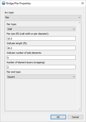
The Bridge/Pier Properties dialog can be accessed by right-clicking a selected arc and selecting the Assign Properties... command. As it starts out, the dialog has the following options in a drop-drown under Arc type:
- "Unassigned" – The default option that contains no properties or attributes.
- "Bridge" – Designates the arc as a bridge structure. When "Bridge" is selected, the dialog has the following options:
- Bridge width (ft) – Set the width (in feet) of the bridge.
- Bridge wrapping width (ft) – Set the wrapping width (in feet) of the bridge.
- Insert bridge entrance/exit (pressure zone) – If this is checked, a bridge entrance and exit will be inserted.
- "Pier" – Designates the arc as a pier structure. When this Arc type is selected, the first option, the Pier type drop-down, will determine what the rest of the options below it are. The Pier type options are:
- "Wall" &nash; When "Wall" is selected as the Pier type, the dialog has the following options:
- Pier size (ft) (wall width or pier diameter) – The size of the pier (in feet), which can be thought of as either the wall width or the pier diameter.
- Wall pier length (ft) – The length of the wall pier (in feet).
- Wall pier number of side elements – The number of side elements of the wall pier.
- Number of element layers (wrapping) – The number of wrapping layer elements.
- Pier end type – This is a drop-down where the end type can be selected from the following options:
- "Square" – A squared off end to the pier.
- "Rounded" – A rounded off end to the pier.
- "Sharp" – A sharp end to the pier.
- "Pier Group" – When "Pier group" is selected as the Pier type, the dialog has the following options:
- Pier size (ft) (wall width or pier diameter) – The size of the pier (in feet), which can be thought of as either the wall width or the pier diameter.
- Number of element layers (wrapping) – The number of wrapping layer elements.
- Number of piers in group – The number of piers contained within the group.
- Pier group spacing (ft) – By how much feet the piers are spaced within the group.
- "Wall" &nash; When "Wall" is selected as the Pier type, the dialog has the following options:
- "Abutment" – Designates the arc as an abutment structure.
Depending on which of these are selected, the options listed below the Arc type will be different.
Related Topics
| [hide] SMS – Surface-water Modeling System | ||
|---|---|---|
| Modules: | 1D Grid • Cartesian Grid • Curvilinear Grid • GIS • Map • Mesh • Particle • Quadtree • Raster • Scatter • UGrid |  |
| General Models: | 3D Structure • FVCOM • Generic • PTM | |
| Coastal Models: | ADCIRC • BOUSS-2D • CGWAVE • CMS-Flow • CMS-Wave • GenCade • STWAVE • WAM | |
| Riverine/Estuarine Models: | AdH • HEC-RAS • HYDRO AS-2D • RMA2 • RMA4 • SRH-2D • TUFLOW • TUFLOW FV | |
| Aquaveo • SMS Tutorials • SMS Workflows | ||

