Lighting Options
From XMS Wiki
(Redirected from Shading Options)
This is the approved revision of this page, as well as being the most recent.
Jump to navigationJump to search
This is the approved revision of this page, as well as being the most recent.
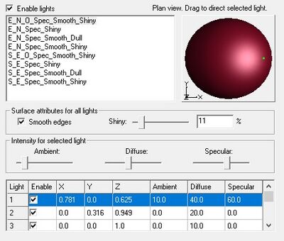
This dialog allows controlling the shading of faces in the GMS, SMS, or WMS display. By default, all objects are displayed in the color specified by their attributes. However, objects such as elements, cells and triangles which cover an area, can be more intuitively understood if they are shaded as a three dimensional entity.
The following table describes the lighting display options.
| Display Option | Description |
|---|---|
| Enable lights | This checkbox controls whether light sources are used in the lighting process for generating lighted images. These light sources control the intensity of the colors on the lighted image and highlight the relief or geometrical variation in the surface of the objects being lighted. |
| Lighting list box | This list contains preset lighting schemes and highlights the scheme currently displayed. |
| Renaming a scheme | Double-click on a scheme to begin editing its name. |
| Deleting a scheme | Right-click on a scheme and select Delete. The final scheme cannot be deleted. |
| Creating a scheme | Right-click on a scheme and select Duplicate. |
| Plan view preview | This preview shows the current light scheme on a sphere in plan view, i.e., looking along the z-axis. Click or drag within the preview to direct both the diffuse and the specular components of the light currently selected in the light table. The selected light direction is shown by a dot on the sphere. A direction from in front of the sphere is shown by a green dot, and from in back by a red dot. |
| Smooth edges | Check this box to smooth all diffuse and specular lights of this scheme so that the surface does not appear faceted. |
| Shiny | Increase this value to sharpen all specular highlights of this scheme. At 100% this value turns off the specular highlight since it assumes that all specular lights are points whose reflection shrinks to a imperceptible point at maximum shininess. At 0% this value assumes that the full intensity of the light is reflected in all directions (decrease the specular values proportionally to get a realistic effect of less and less light reflecting to the eye from each surface). |
| Ambient slider | Shows the ambient value of the light currently selected in the table, and can change the value. The ambient value is light from all directions which lights each and all surfaces uniformly leaving no surface unlighted. It is most useful on surfaces facing away from directional light such as diffuse and specular light. |
| Diffuse slider | Shows the diffuse value of the light currently selected in the table, and can change the value. The diffuse value is for a point light which brightens surfaces in all directions the more they face that light, and which leaves surfaces in darkness that face away from the light. |
| Specular slider | Shows the specular value of the light currently selected in the table, and can change the value. The specular value is a point light which brightens surfaces if they reflect like a mirror from the direction of the light to the direction of the viewer, and which leaves surfaces in darkness that do not have this angle of reflection. |
| Light table | Displays the enable, xyz position, Ambient, Diffuse, and Specular values for each of 8 lights in the current scheme, and highlights the currently selected light. Any of these values may be modified by clicking them and editing their value. |
| Enable column | Check these boxes to turn on each light. |
| X, Y, and Z columns | Edit these values or click/drag in the plan view preview sphere to change the direction of the light. These values are normalized to a unit direction vector. |
| Ambient, Diffuse, and Specular columns | Edit these values or drag their corresponding slider. |
GMS – Groundwater Modeling System | ||
|---|---|---|
| Modules: | 2D Grid • 2D Mesh • 2D Scatter Point • 3D Grid • 3D Mesh • 3D Scatter Point • Boreholes • GIS • Map • Solid • TINs • UGrids | |
| Models: | FEFLOW • FEMWATER • HydroGeoSphere • MODAEM • MODFLOW • MODPATH • mod-PATH3DU • MT3DMS • MT3D-USGS • PEST • PHT3D • RT3D • SEAM3D • SEAWAT • SEEP2D • T-PROGS • ZONEBUDGET | |
| Aquaveo | ||
SMS – Surface-water Modeling System | ||
|---|---|---|
| Modules: | 1D Grid • Cartesian Grid • Curvilinear Grid • GIS • Map • Mesh • Particle • Quadtree • Raster • Scatter • UGrid |  |
| General Models: | 3D Structure • FVCOM • Generic • PTM | |
| Coastal Models: | ADCIRC • BOUSS-2D • CGWAVE • CMS-Flow • CMS-Wave • GenCade • STWAVE • WAM | |
| Riverine/Estuarine Models: | AdH • HEC-RAS • HYDRO AS-2D • RMA2 • RMA4 • SRH-2D • TUFLOW • TUFLOW FV | |
| Aquaveo • SMS Tutorials • SMS Workflows | ||
