SMS:TUFLOW Coverages: Difference between revisions
| (181 intermediate revisions by the same user not shown) | |||
| Line 1: | Line 1: | ||
TUFLOW models use several types of [[SMS:Coverages|Feature coverages]]. | {{TOCright}} | ||
TUFLOW models use several types of [[SMS:Coverages|Feature coverages]]. Coverages are used in SMS to represent geometry and associated attributes as points, arcs, and polygons. Unlike some models used in SMS, TUFLOW uses coverage data as model inputs. | |||
TUFLOW coverages can be associated with [[SMS:TUFLOW 2D Geometry Components | 2D | TUFLOW coverages can be associated with [[SMS:TUFLOW 2D Geometry Components | 2D geometry components]] and [[SMS:TUFLOW Simulation|TUFLOW simulations]] by creating links to the coverage in the component or simulation. The use of links allows multiple simulations or geometry components to share coverage data. Sharing data between simulations reduces required disk space for the simulation and makes it easier to update several simulations with the same changes. | ||
In addition to the coverages listed below, TUFLOW models can use [[SMS:Area Property Coverage|Area Property | In addition to the coverages listed below, TUFLOW models can use [[SMS:Area Property Coverage|Area Property coverages]] to define where to use specific material properties using polygons. | ||
== | ==Grid Extents Coverage== | ||
A TUFLOW 2D Grid Extents coverage is used to create TUFLOW grids. TUFLOW grids are generated by creating and positioning a Cartesian [[SMS:Grid Frame Properties|grid frame]] and then right-clicking on the coverage and choosing '''Map→2D Grid'''. | |||
==Boundary Conditions Coverage== | |||
A boundary condition definition consists of a boundary condition category and one or more boundary condition components. TUFLOW supports the ability to combine multiple definitions into a single curve. Component names must be unique for a project. | |||
Boundary conditions (BC) are defined in TUFLOW with points, arcs, or polygons in a 1D–2D BCs and Links coverage. Boundary condition coverages can also be used to specify cell code (active/inactive) areas of the 2D model domain. The kinds of boundary conditions available depend upon whether it is applied to a point, arc or polygon. | |||
Boundary conditions defined at points are 1D boundary conditions and must be placed at the same location as a 1D boundary node. (See [[SMS:Feature Object Modification: All|Snapping Feature Objects]]) The boundary condition information is specified in the ''BC Node Attributes'' dialog (see [[SMS:TUFLOW_Boundary_Conditions#1D_Boundary_Conditions_at_Nodes|1D Boundary Conditions at Nodes]]). | |||
Arcs can be used to define 2D boundary conditions applied to the 2D domain. The boundary condition attributes are specified in the ''BC Arc Attributes'' dialog (see [[SMS:TUFLOW_Boundary_Conditions#2D_Boundary_Conditions_at_Arcs|2D Boundary Conditions at Arcs]]). | |||
Polygons can be used to define rainfall applied to 2D domains or to specify active/inactive information for 2D domains. The ''BC Polygon Attributes'' dialog specifies the type of information stored with the polygons (see [[SMS:TUFLOW_Boundary_Conditions#2D_Boundary_Conditions_for_Polygons|2D Boundary Conditions at Polygons]]). | |||
[[Category:SMS Boundary Conditions|T]] | |||
==2D Materials Coverage== | |||
On this coverage polygons can be created to define material areas. This is the same as the [[SMS:Area Property Coverage|Area Properties coverage]]. | |||
== | ==1D/2D Connections Coverage== | ||
1D | [[File:TUFLOW ConnectionArcAttributes.png|thumb|250 px|TUFLOW 1D–2D connection ''Arc Attributes'' dialog]] | ||
1D–2D connections are used with the 2D Boundary Condition coverage [[SMS:TUFLOW Combining 1D and 2D Domains|to link 2D and 1D domains]]. | |||
Two types of arcs can be created in a 1D–2D Connection coverage: 1D/2D connection arcs (CN) and Flow vs. Head Connection arcs (SC). The type of arc is assigned by selecting the desired arc and using the ''Feature Objects'' | '''Attributes''' command to bring up the ''Arc Attributes'' dialog for this coverage. Designate the arc ''Connection type'' in the dialog. There is also an option to apply ''Weighting'' to 1D–2D connection arcs. Weighting sets the proportion to be applied in distributing the water level from the 1D node to the 2D cell. | |||
1D–2D connection arcs are written to a 2d_bc layer file for TUFLOW input (see 2D BC Layers in the TUFLOW documentation). One end of the connection arcs must end at the same location as a 1D Flow/2D Water Level Connection (HX) in a TUFLOW Boundary Conditions coverage. The other end of the connection arc must end at the same location as a network node in a TUFLOW Network coverage. | |||
The | The coverage has a couple coverage specific commands that appear when right-clicking on the 1D–2D Connections coverage. The commands are: | ||
; 1D–2D Connection Properties : Brings ups a ''Select Boundary Condition Coverage'' dialog where a Boundary Condition coverage can be assigned to the Connection coverage. | |||
; Clean Connections : Opens a ''Clean Options'' dialog. | |||
= | {| | ||
|- | |||
|valign="top"|[[File:TUFLOW SelectBC.png|thumb|none|225 px|TUFLOW ''Select Boundary Condition Coverage'' dialog]] | |||
|[[File:TUFLOW CleanConnections.png|thumb|none|225 px|TUFLOW ''Clean Options'' dialog]] | |||
|} | |||
==TUFLOW | ===TUFLOW Clean Options=== | ||
This dialog makes sure that connections arcs end at HX boundaries and the HX boundaries have nodes at the connection endpoints. The dialog has the following options: | |||
*''Tolerance'' – Determines the tolerance level SMS will use in determining if the connection arcs end at the HX boundaries. | |||
*''2D BC coverage'' – Sets the Boundary Condition coverage that will provide the HX boundary. The coverage is selected in the tree below. | |||
*''1D Network coverage'' – Sets the Network coverage to be used. The coverage is selected in the tree below. | |||
==1D Cross Section Coverage== | |||
Cross section coverages are used to define open channel cross section data for 1D networks. Cross section geometry is generally extracted from a TIN and may be edited by hand if desired. | |||
Cross sections are created by creating arcs in a cross section coverage. SMS can automatically create cross section arcs from a 1D network. | |||
This coverage has a few unique commands available when right-clicking on the coverage in the Project Explorer. The commands are: | |||
; Extract from Scatter : Extracts the elevations for the arc from a scatter set (TIN) after cross section arcs are created. This will extract the cross section data from the active dataset on the active scatter set. Values are extracted at each triangle edge in the scatter set and each node or vertex on the cross section arc. | |||
; Map Materials from Area Property Coverage : Maps the materials from an area property coverage to the cross sections after cross sections have been created. | |||
; Add Arcs to Mesh : If there is an existing mesh, adds the cross section arcs to the active mesh. | |||
; Cross Sections Properties: Opens the [[SMS:Managing Cross Sections|''CsDb Management'']] dialog. All the cross sections in the coverage are stored in a cross section database. (see [[SMS:Editing Cross Sections|Editing Cross Sections]]). | |||
; Trim to Code Polygon : Trims the cross sections to the code polygons in the boundary condition coverage. This is done automatically if there is only one boundary condition coverage. If working with a project that uses more than one such coverage, a ''Select Coverage'' dialog will appear to allow choosing a coverage. | |||
; Refresh Cross Section Database Materials List : If there have been changes to the material list in the cross section database, this command with update the coverage to match. | |||
Individual cross sections may be viewed and edited by double-clicking on an arc, or by selecting an arc and choosing ''Feature Objects'' | '''Attributes'''. This will bring up the ''Cross Section Attributes'' dialog. | |||
[[Image:TUFLOW Cross-Section.png|thumb|none|left|175 px|''TUFLOW Cross Section'' dialog]] | |||
==1D Network Coverage== | |||
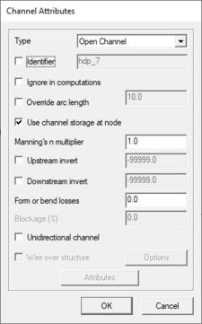
[[Image:TUFLOW Channel Attributes.png|thumb|225 px|TUFLOW ''Channel Attributes'' dialog]] | |||
1D domains are made up of a network of channels and nodes. Channels represent the conveyance of the flowpaths and nodes represent the storage of inundated areas (TUFLOW Users Manual). Channels are created using arcs and the arc endpoints are the nodes. | |||
There are a variety of channel types including open channels, weirs, and culverts (pipe networks). The channel also has a variety of attributes depending upon the channel type. The channel type and attributes are defined in the ''Channel Attributes'' dialog which can be reached by selecting an arc and using the ''Feature Objects'' | '''Atributes''' command. | |||
There are two types of nodes generic nodes, and inlets. Generic nodes can be used to specify storage and can be used to set channel invert elevations. Inlet nodes are used to get flows from a 2D domain into a 1D pipe network below the 2D domain. The node type and attributes are defined in the ''Network Node Attributes'' dialog reached by selecting a node and using the ''Feature Objects'' | '''Attributes''' command. | |||
TUFLOW | The TUFLOW documentation sections "5.12.4: Connecting Pits and Nodes to 2D Domains" and "5.4: 1d_nwk Attributes" list some new TUFLOW features that SMS now supports. SMS's [[SMS:TUFLOW Network Node Attributes|''Network Node Attributes'']] dialog has several new additions to the ''Create Connection to 2D Domain (SX)'' section. These new options allow controlling elevations at the connections, how many cells are connected, and the method for selection of additional cells (Grade or Sag). Each option correlates fairly directly to a TUFLOW field and some are labeled as such to make look-up easy. | ||
The coverage also has a few unique commands accessed by right-clicking on the coverage in the Project Explorer. These are: | |||
; Add Arcs to Mesh : If there is an existing mesh, adds the cross section arcs to the active mesh. | |||
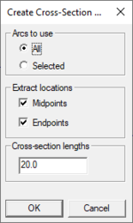
; Create Cross Section Arcs : Brings up the ''Create Cross Sections Arcs'' dialog where cross sections arcs can be automatically generated in the coverage. | |||
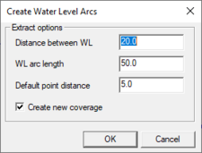
; Create Water Level Arcs : Brings up the ''Create Water Level Arcs'' dialog where water level arcs can be automatically generated in the coverage. | |||
{| | |||
{| | |||
|- | |- | ||
|[[File:TUFLOW CreateCrossSectionArcs.png|thumb|none|150 px|The TUFLOW ''Create Cross Section Arcs'' dialog]] | |||
|valign="top"|[[File:TUFLOW CreateWaterLevelArcs.png|thumb|none|225 px|The TUFLOW ''Create Water Level Arcs'' dialog]] | |||
| | |||
| | |||
| | |||
| | |||
| | |||
| | |||
| | |||
| | |||
| | |||
| | |||
| | |||
|} | |} | ||
==2D/2D Linkages Coverage== | |||
Any number of grids of varying sizes and/or orientations may be used in TUFLOW. A 2D/2D Linkages coverage is used to setup TUFLOW to use multiple 2D domains. | |||
Polygons are created on this coverage that enclose each domain. Then each polygon can be assigned to a domain by using the ''Feature Objects'' | '''Attributes''' command to bring up a ''Select TUFLOW Grid'' dialog. | |||
[[ | See [[SMS:TUFLOW Linking 2D Domains|TUFLOW Linking 2D Domains]] for more information. | ||
== | ==2D Flow Constriction Shapes Coverage== | ||
A 2D Flow Constriction Shapes coverage is used to define flow constrictions in TUFLOW. These are used to model hydraulic structures or other sources of additional losses in TUFLOW. Flow constrictions are of two categories: standard (non-layered) and layered flow constrictions. Layered flow constrictions can be used to model situations where flow has multiple pathways at different elevations. Examples would include flow under a bridge and over the bridge deck as well as a pipeline (typically large box culverts to model as 2D) crossing a waterway. The standard (non-layered) flow constrictions can model box culverts, floating bridge decks, bridges, or apply additional form losses to an area (due to submodel scale features). Flow constrictions can be created for arcs or polygons. | |||
Note that this coverage is different from the older (and outdated) 2D Flow Constriction coverage, which is still supported. | |||
For more information on using this coverage, see [[SMS:TUFLOW Flow Constriction Shapes|TUFLOW Flow Constriction Shapes]]. | |||
==2D Miscellaneous Coverage== | |||
[[File:TUFLOW Misc CoverageProperties.png|thumb|225 px|The TUFLOW miscellaneous ''Coverage Properties'' dialog]] | |||
[[File:TUFLOW Misc PolyProp.png|thumb|225 px|TUFLOW miscellaneous coverage polygon properties dialog for the ''Initial Water Level'' coverage type]] | |||
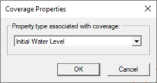
Spatially varied attributes can be defined using the 2D Miscellaneous (FLC, WRF, IWL, SRF and AD) coverage. When creating this coverage, the coverage type needs to be set in the ''Coverage Properties'' dialog. This dialog can be reached by right-clicking on the coverage in the Project Explorer and selecting the '''Properties''' command. | |||
[[ | The available spatial attributes are: | ||
* "Initial Water Level (IWL)" – Initial water levels at the start of the model simulation. Assigning spatially varied initial water levels may be necessary to ensure that water bodies have water in them initially. | |||
* "Weir Factor (WRF)" – Allows calibration or adjustment where the broad-crested weir equation is applied. A value of zero removes automatic weir calculations. | |||
* "Form Loss Coefficient (FLC)" – Applies the form loss attribute values to all cells within each region. Note that FLC values will need to be changed if the 2D cell size changes. | |||
* "Storage Reduction Factor (SRF)" – Reduces the area in the cell available for water. | |||
* "AD Initial Condition (AD)" – Defines the spatial distribution of initial conditions for a given constituent. (See [[SMS:TUFLOW AD|TUFLOW AD]]) | |||
* "AD Minimum Dispersion (AD)" – Defines the spatial distribution of minimum dispersion coefficients for a given constituent. (See [[SMS:TUFLOW AD|TUFLOW AD]]) | |||
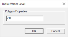
TUFLOW | The values for the attributes are assigned to polygons created in the coverage. TUFLOW assigns the values from the polygons to the cells that exist within the polygon. Selecting a polygon and using the ''Feature Objects'' | '''Attributes''' command will being up a dialog with the value can be assigned. The name of the dialog will match the coverage property type. | ||
== | ==2D Z Lines (Advanced) Coverage== | ||
The 2D Z Lines (Advanced) coverage is | The 2D Z Lines (Advanced) Coverage allows modifying terrain along an arc or arcs, but has additional options. With the 2D Z Lines (Advanced) coverage, modify geometry through time to simulate levee failures or other changes to elevation data within the model run. These changes are set up start when a "trigger" is activated such as at a specific time during the simulation or when water depth exceeds a certain amount. An example application is a levee collapsing when flood water overtops it. | ||
[[File:ZShape failing levee.jpg|thumb|400 px|Failing levee]] | |||
* Make sure the coverage is in the [[SMS:TUFLOW 2D Geometry Components|geometry component(s)]] that is to be applied to the modification. | |||
ZShapes | TUFLOW also supports the features described above using polygon ZShapes. However, SMS does not support polygon ZShapes using these advanced features (such as triggers) at this time. If necessary to create static modifications to terrain using polygons, use the 2D Z Lines/Polygons (Simple) coverage. | ||
The 2D Z Lines (Advanced) coverage is available under the models/TUFLOW folder. ZShape data is stored in a feature arc's attributes. The Z values of the feature arc's points determine its Z, not the Z of the arc itself (exceptions to this are explained in the [[SMS:TUFLOW_ZShape#Arc_Properties_Dialog|Arc Properties Dialog]] article). | |||
ZShapes are split into two main categories, Static ZShapes and Variable ZShapes. Static ZShapes are simple terrain modifications that do not change over time. They can be used to create a levee, pit, sand bar, dam, etc. Variable ZShapes have a trigger that causes them to raise or lower the terrain during the simulation. Often a variable ZShape is combined with a static one to provide raised terrain for the trigger to modify. This is necessary because a variable z shape cannot raise the same area it intends to lower when its trigger activates -- it needs the terrain to already be there and cannot create it itself, only modify once its trigger activates. | |||
See [[SMS:TUFLOW ZShape|TUFLOW ZShape]] for more information. | |||
== | ==2D Z Lines/Polygons (Simple) Coverage== | ||
These coverages are used as geometry modifications and force grid elevation values using arcs or polygons. This can be useful to ensure ridge or gully lines are represented in the model, simulate a proposed levy, or to simulate a proposed fill/excavation scenario. | These coverages are used as geometry modifications and force grid elevation values using arcs or polygons. This can be useful to ensure ridge or gully lines are represented in the model, simulate a proposed levy, or to simulate a proposed fill/excavation scenario. | ||
It is possible to only have the elevations assigned from a feature object if the feature elevation is higher or lower (user specified) than the existing elevations in the grid. This is controlled in the ''2D Z Lines/Polygons (Simple) Coverage Properties'' dialog (right-click on the coverage and choose '''Properties'''). | |||
The options specified in the coverage properties dialog apply to any geometry modification arcs and polygons within the coverage. If wanting to use multiple settings within a simulation, there must be multiple 2D z line/polygon (simple) coverages. | |||
[[Image:TUFLOW Z Values Options.png|thumb|225 px|TUFLOW 2D Z Lines/Polygons (Simple) Coverage Properties Z Values ''Options'' dialog]] | |||
===Z Values=== | ===Z Values=== | ||
The z values determine how the elevations in the coverage are used to modify the existing model elevations. The options are: | The z values determine how the elevations in the coverage are used to modify the existing model elevations. The options are: | ||
| Line 270: | Line 146: | ||
If this option is not selected, the z values of the arc will be applied to the nearest elevation locations in each cell that the arc passes through. Otherwise, the arc elevations will be applied to every elevation location in each cell that the arc passes through. | If this option is not selected, the z values of the arc will be applied to the nearest elevation locations in each cell that the arc passes through. Otherwise, the arc elevations will be applied to every elevation location in each cell that the arc passes through. | ||
Make sure the coverage is in the Geometry Component(s) that is to be applied to the modification. | |||
; Points : Points are ignored in the geometry modification coverage. | |||
Points are ignored in the geometry modification coverage. | ; Arcs : [[Image:TUFLOW Choose Arc Type.png|thumb|225 px|TUFLOW ''Choose Arc Type'' dialog]] Only the elevations at the nodes (endpoints) are used to set the grid elevations. Vertex (intermediate) elevations are ignored. Cell elevations along the arc will be interpolated linearly based on distance from the endpoint elevation. If wanting to specify elevations at vertices on an arc, convert the arc vertices to nodes to create multiple arcs joined end to end. | ||
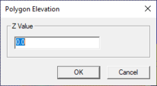
; Polygons : To set the elevation for polygons double-click on the polygon and enter the elevation in the ''Polygon Elevation'' dialog. This elevation will be applied to all cells within the polygon. This dialog can also be accessed by right-clicking on a polygon and selecting '''Attributes''' for the right-click menu. | |||
:[[File:TUFLOW Z Value.png|thumb|none|left|225 px|TUFLOW ''Polygon Elevation'' dialog]] | |||
== | ==Water Level Lines Coverage== | ||
[[Image:TUFLOW Water Level Arc Att.png|thumb|225 px|TUFLOW ''Water Lever Arc Attributes'' dialog]] | |||
Water level line coverages define the locations where 1D solutions will be written as 2D output. TUFLOW creates water level points along the water level lines. The water level lines in conjunction with the water level points guide TUFLOW on how to represent the 1D flow in the 2D domain. | |||
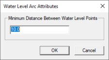
Arcs are the only objects used in the water level lines coverage. The only attribute in the water level lines coverage is the minimum distance between water level points. This is used by TUFLOW to generate the water level points along the arcs. To change this attribute, double-click on an arc or right-click and select ''Attributes'' from the right-click menu. This brings up the ''Water Level Arc Attributes'' dialog. | |||
To | |||
Right-clicking on the coverage in the Project Explorer has the following option: | |||
; Trim to Code Polygon : Trims the water lines to the code polygons in the boundary condition coverage. This is done automatically if there is only one boundary condition coverage. If working with a project that uses more than one such coverage, a ''Select Coverage'' dialog will appear to allow choosing a coverage. | |||
For more information about how TUFLOW uses water level lines to generate 2D flows see TUFLOW Water Level Points Coverage. | For more information about how TUFLOW uses water level lines to generate 2D flows see TUFLOW Water Level Points Coverage. | ||
== | ==Water Level Points Coverage== | ||
Water level points are used in conjunction with water level lines to guide TUFLOW on creating 2D output for 1D networks (see TUFLOW Water Level Lines Coverage). | Water level points are used in conjunction with water level lines to guide TUFLOW on creating 2D output for 1D networks (see TUFLOW Water Level Lines Coverage). | ||
Water level points store a material value. This material value along with the z location of each point is used by TUFLOW to better approximate 2D flow along a water level line. TUFLOW performs a parallel channel analysis so that flow rates reported in the 2D output vary based upon the depth and roughness of a channel. Areas that are more rough and shallow than other areas will have a smaller flow rate than other areas along the same water level line. | Water level points store a material value. This material value along with the z location of each point is used by TUFLOW to better approximate 2D flow along a water level line. TUFLOW performs a parallel channel analysis so that flow rates reported in the 2D output vary based upon the depth and roughness of a channel. Areas that are more rough and shallow than other areas will have a smaller flow rate than other areas along the same water level line. | ||
The material value for each point can be mapped from an area property coverage by right-clicking on the coverage tree item and selecting ''Materials for Area Coverage''. By default the elevation of each point is based upon the neighboring cross | The material value for each point can be mapped from an area property coverage by right-clicking on the coverage tree item and selecting '''Materials for Area Coverage'''. By default the elevation of each point is based upon the neighboring cross section information. | ||
====Creating the Water Level Points Coverage==== | ====Creating the Water Level Points Coverage==== | ||
| Line 315: | Line 175: | ||
The initial water level points coverage data is created by TUFLOW during a run. Once a run has been completed, the data can be read from the check file that starts with the simulation name and ends with _WLLp_check.mif (see [[SMS:TUFLOW Check Files|TUFLOW check files]]). Open this file from SMS and select TUFLOW WLL Points from the combo-box that comes up. This coverage now can be included in simulations to provide additional guidance to TUFLOW in distributing 1D flows. | The initial water level points coverage data is created by TUFLOW during a run. Once a run has been completed, the data can be read from the check file that starts with the simulation name and ends with _WLLp_check.mif (see [[SMS:TUFLOW Check Files|TUFLOW check files]]). Open this file from SMS and select TUFLOW WLL Points from the combo-box that comes up. This coverage now can be included in simulations to provide additional guidance to TUFLOW in distributing 1D flows. | ||
==Related Topics== | |||
* [[SMS:TUFLOW|TUFLOW model]] | |||
{{Template:Navbox SMS}} | {{Template:Navbox SMS}} | ||
[[Category:TUFLOW|Coverages]] | [[Category:TUFLOW|Coverage]] | ||
[[Category:TUFLOW Dialogs|Cover]] | |||
[[Category:SMS Coverages|TUFLOW]] | |||
[[Category:SMS Map|TUFLOW]] | |||
Latest revision as of 16:59, 23 September 2019
TUFLOW models use several types of Feature coverages. Coverages are used in SMS to represent geometry and associated attributes as points, arcs, and polygons. Unlike some models used in SMS, TUFLOW uses coverage data as model inputs.
TUFLOW coverages can be associated with 2D geometry components and TUFLOW simulations by creating links to the coverage in the component or simulation. The use of links allows multiple simulations or geometry components to share coverage data. Sharing data between simulations reduces required disk space for the simulation and makes it easier to update several simulations with the same changes.
In addition to the coverages listed below, TUFLOW models can use Area Property coverages to define where to use specific material properties using polygons.
Grid Extents Coverage
A TUFLOW 2D Grid Extents coverage is used to create TUFLOW grids. TUFLOW grids are generated by creating and positioning a Cartesian grid frame and then right-clicking on the coverage and choosing Map→2D Grid.
Boundary Conditions Coverage
A boundary condition definition consists of a boundary condition category and one or more boundary condition components. TUFLOW supports the ability to combine multiple definitions into a single curve. Component names must be unique for a project.
Boundary conditions (BC) are defined in TUFLOW with points, arcs, or polygons in a 1D–2D BCs and Links coverage. Boundary condition coverages can also be used to specify cell code (active/inactive) areas of the 2D model domain. The kinds of boundary conditions available depend upon whether it is applied to a point, arc or polygon.
Boundary conditions defined at points are 1D boundary conditions and must be placed at the same location as a 1D boundary node. (See Snapping Feature Objects) The boundary condition information is specified in the BC Node Attributes dialog (see 1D Boundary Conditions at Nodes).
Arcs can be used to define 2D boundary conditions applied to the 2D domain. The boundary condition attributes are specified in the BC Arc Attributes dialog (see 2D Boundary Conditions at Arcs).
Polygons can be used to define rainfall applied to 2D domains or to specify active/inactive information for 2D domains. The BC Polygon Attributes dialog specifies the type of information stored with the polygons (see 2D Boundary Conditions at Polygons).
2D Materials Coverage
On this coverage polygons can be created to define material areas. This is the same as the Area Properties coverage.
1D/2D Connections Coverage
1D–2D connections are used with the 2D Boundary Condition coverage to link 2D and 1D domains.
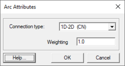
Two types of arcs can be created in a 1D–2D Connection coverage: 1D/2D connection arcs (CN) and Flow vs. Head Connection arcs (SC). The type of arc is assigned by selecting the desired arc and using the Feature Objects | Attributes command to bring up the Arc Attributes dialog for this coverage. Designate the arc Connection type in the dialog. There is also an option to apply Weighting to 1D–2D connection arcs. Weighting sets the proportion to be applied in distributing the water level from the 1D node to the 2D cell.
1D–2D connection arcs are written to a 2d_bc layer file for TUFLOW input (see 2D BC Layers in the TUFLOW documentation). One end of the connection arcs must end at the same location as a 1D Flow/2D Water Level Connection (HX) in a TUFLOW Boundary Conditions coverage. The other end of the connection arc must end at the same location as a network node in a TUFLOW Network coverage.
The coverage has a couple coverage specific commands that appear when right-clicking on the 1D–2D Connections coverage. The commands are:
- 1D–2D Connection Properties
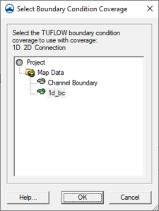
- Brings ups a Select Boundary Condition Coverage dialog where a Boundary Condition coverage can be assigned to the Connection coverage.
- Clean Connections
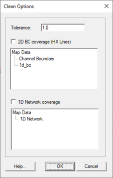
- Opens a Clean Options dialog.
TUFLOW Clean Options
This dialog makes sure that connections arcs end at HX boundaries and the HX boundaries have nodes at the connection endpoints. The dialog has the following options:
- Tolerance – Determines the tolerance level SMS will use in determining if the connection arcs end at the HX boundaries.
- 2D BC coverage – Sets the Boundary Condition coverage that will provide the HX boundary. The coverage is selected in the tree below.
- 1D Network coverage – Sets the Network coverage to be used. The coverage is selected in the tree below.
1D Cross Section Coverage
Cross section coverages are used to define open channel cross section data for 1D networks. Cross section geometry is generally extracted from a TIN and may be edited by hand if desired.
Cross sections are created by creating arcs in a cross section coverage. SMS can automatically create cross section arcs from a 1D network.
This coverage has a few unique commands available when right-clicking on the coverage in the Project Explorer. The commands are:
- Extract from Scatter
- Extracts the elevations for the arc from a scatter set (TIN) after cross section arcs are created. This will extract the cross section data from the active dataset on the active scatter set. Values are extracted at each triangle edge in the scatter set and each node or vertex on the cross section arc.
- Map Materials from Area Property Coverage
- Maps the materials from an area property coverage to the cross sections after cross sections have been created.
- Add Arcs to Mesh
- If there is an existing mesh, adds the cross section arcs to the active mesh.
- Cross Sections Properties
- Opens the CsDb Management dialog. All the cross sections in the coverage are stored in a cross section database. (see Editing Cross Sections).
- Trim to Code Polygon
- Trims the cross sections to the code polygons in the boundary condition coverage. This is done automatically if there is only one boundary condition coverage. If working with a project that uses more than one such coverage, a Select Coverage dialog will appear to allow choosing a coverage.
- Refresh Cross Section Database Materials List
- If there have been changes to the material list in the cross section database, this command with update the coverage to match.
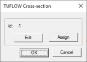
Individual cross sections may be viewed and edited by double-clicking on an arc, or by selecting an arc and choosing Feature Objects | Attributes. This will bring up the Cross Section Attributes dialog.
1D Network Coverage
1D domains are made up of a network of channels and nodes. Channels represent the conveyance of the flowpaths and nodes represent the storage of inundated areas (TUFLOW Users Manual). Channels are created using arcs and the arc endpoints are the nodes.
There are a variety of channel types including open channels, weirs, and culverts (pipe networks). The channel also has a variety of attributes depending upon the channel type. The channel type and attributes are defined in the Channel Attributes dialog which can be reached by selecting an arc and using the Feature Objects | Atributes command.
There are two types of nodes generic nodes, and inlets. Generic nodes can be used to specify storage and can be used to set channel invert elevations. Inlet nodes are used to get flows from a 2D domain into a 1D pipe network below the 2D domain. The node type and attributes are defined in the Network Node Attributes dialog reached by selecting a node and using the Feature Objects | Attributes command.
The TUFLOW documentation sections "5.12.4: Connecting Pits and Nodes to 2D Domains" and "5.4: 1d_nwk Attributes" list some new TUFLOW features that SMS now supports. SMS's Network Node Attributes dialog has several new additions to the Create Connection to 2D Domain (SX) section. These new options allow controlling elevations at the connections, how many cells are connected, and the method for selection of additional cells (Grade or Sag). Each option correlates fairly directly to a TUFLOW field and some are labeled as such to make look-up easy.
The coverage also has a few unique commands accessed by right-clicking on the coverage in the Project Explorer. These are:
- Add Arcs to Mesh
- If there is an existing mesh, adds the cross section arcs to the active mesh.
- Create Cross Section Arcs
- Brings up the Create Cross Sections Arcs dialog where cross sections arcs can be automatically generated in the coverage.
- Create Water Level Arcs
- Brings up the Create Water Level Arcs dialog where water level arcs can be automatically generated in the coverage.
2D/2D Linkages Coverage
Any number of grids of varying sizes and/or orientations may be used in TUFLOW. A 2D/2D Linkages coverage is used to setup TUFLOW to use multiple 2D domains.
Polygons are created on this coverage that enclose each domain. Then each polygon can be assigned to a domain by using the Feature Objects | Attributes command to bring up a Select TUFLOW Grid dialog.
See TUFLOW Linking 2D Domains for more information.
2D Flow Constriction Shapes Coverage
A 2D Flow Constriction Shapes coverage is used to define flow constrictions in TUFLOW. These are used to model hydraulic structures or other sources of additional losses in TUFLOW. Flow constrictions are of two categories: standard (non-layered) and layered flow constrictions. Layered flow constrictions can be used to model situations where flow has multiple pathways at different elevations. Examples would include flow under a bridge and over the bridge deck as well as a pipeline (typically large box culverts to model as 2D) crossing a waterway. The standard (non-layered) flow constrictions can model box culverts, floating bridge decks, bridges, or apply additional form losses to an area (due to submodel scale features). Flow constrictions can be created for arcs or polygons.
Note that this coverage is different from the older (and outdated) 2D Flow Constriction coverage, which is still supported.
For more information on using this coverage, see TUFLOW Flow Constriction Shapes.
2D Miscellaneous Coverage
Spatially varied attributes can be defined using the 2D Miscellaneous (FLC, WRF, IWL, SRF and AD) coverage. When creating this coverage, the coverage type needs to be set in the Coverage Properties dialog. This dialog can be reached by right-clicking on the coverage in the Project Explorer and selecting the Properties command.
The available spatial attributes are:
- "Initial Water Level (IWL)" – Initial water levels at the start of the model simulation. Assigning spatially varied initial water levels may be necessary to ensure that water bodies have water in them initially.
- "Weir Factor (WRF)" – Allows calibration or adjustment where the broad-crested weir equation is applied. A value of zero removes automatic weir calculations.
- "Form Loss Coefficient (FLC)" – Applies the form loss attribute values to all cells within each region. Note that FLC values will need to be changed if the 2D cell size changes.
- "Storage Reduction Factor (SRF)" – Reduces the area in the cell available for water.
- "AD Initial Condition (AD)" – Defines the spatial distribution of initial conditions for a given constituent. (See TUFLOW AD)
- "AD Minimum Dispersion (AD)" – Defines the spatial distribution of minimum dispersion coefficients for a given constituent. (See TUFLOW AD)
The values for the attributes are assigned to polygons created in the coverage. TUFLOW assigns the values from the polygons to the cells that exist within the polygon. Selecting a polygon and using the Feature Objects | Attributes command will being up a dialog with the value can be assigned. The name of the dialog will match the coverage property type.
2D Z Lines (Advanced) Coverage
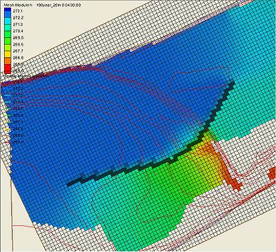
The 2D Z Lines (Advanced) Coverage allows modifying terrain along an arc or arcs, but has additional options. With the 2D Z Lines (Advanced) coverage, modify geometry through time to simulate levee failures or other changes to elevation data within the model run. These changes are set up start when a "trigger" is activated such as at a specific time during the simulation or when water depth exceeds a certain amount. An example application is a levee collapsing when flood water overtops it.
- Make sure the coverage is in the geometry component(s) that is to be applied to the modification.
TUFLOW also supports the features described above using polygon ZShapes. However, SMS does not support polygon ZShapes using these advanced features (such as triggers) at this time. If necessary to create static modifications to terrain using polygons, use the 2D Z Lines/Polygons (Simple) coverage.
The 2D Z Lines (Advanced) coverage is available under the models/TUFLOW folder. ZShape data is stored in a feature arc's attributes. The Z values of the feature arc's points determine its Z, not the Z of the arc itself (exceptions to this are explained in the Arc Properties Dialog article).
ZShapes are split into two main categories, Static ZShapes and Variable ZShapes. Static ZShapes are simple terrain modifications that do not change over time. They can be used to create a levee, pit, sand bar, dam, etc. Variable ZShapes have a trigger that causes them to raise or lower the terrain during the simulation. Often a variable ZShape is combined with a static one to provide raised terrain for the trigger to modify. This is necessary because a variable z shape cannot raise the same area it intends to lower when its trigger activates -- it needs the terrain to already be there and cannot create it itself, only modify once its trigger activates.
See TUFLOW ZShape for more information.
2D Z Lines/Polygons (Simple) Coverage
These coverages are used as geometry modifications and force grid elevation values using arcs or polygons. This can be useful to ensure ridge or gully lines are represented in the model, simulate a proposed levy, or to simulate a proposed fill/excavation scenario.
It is possible to only have the elevations assigned from a feature object if the feature elevation is higher or lower (user specified) than the existing elevations in the grid. This is controlled in the 2D Z Lines/Polygons (Simple) Coverage Properties dialog (right-click on the coverage and choose Properties). The options specified in the coverage properties dialog apply to any geometry modification arcs and polygons within the coverage. If wanting to use multiple settings within a simulation, there must be multiple 2D z line/polygon (simple) coverages.
Z Values
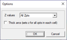
The z values determine how the elevations in the coverage are used to modify the existing model elevations. The options are:
- All Zpts (default) – The z values from all of the arcs/polygons are used.
- Min – The z values from the arcs/polygons will only overwrite the existing elevations if the elevations are lower.
- Max – The z values from the arcs/polygons will only overwrite the existing elevations if the elevations are higher.
- Add – The z value becomes the existing elevation plus the z value from the arc/polygon (which may be negative).
Thick Arcs
If this option is not selected, the z values of the arc will be applied to the nearest elevation locations in each cell that the arc passes through. Otherwise, the arc elevations will be applied to every elevation location in each cell that the arc passes through.
Make sure the coverage is in the Geometry Component(s) that is to be applied to the modification.
- Points
- Points are ignored in the geometry modification coverage.
- Arcs
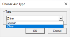
- Only the elevations at the nodes (endpoints) are used to set the grid elevations. Vertex (intermediate) elevations are ignored. Cell elevations along the arc will be interpolated linearly based on distance from the endpoint elevation. If wanting to specify elevations at vertices on an arc, convert the arc vertices to nodes to create multiple arcs joined end to end.
- Polygons
- To set the elevation for polygons double-click on the polygon and enter the elevation in the Polygon Elevation dialog. This elevation will be applied to all cells within the polygon. This dialog can also be accessed by right-clicking on a polygon and selecting Attributes for the right-click menu.
Water Level Lines Coverage
Water level line coverages define the locations where 1D solutions will be written as 2D output. TUFLOW creates water level points along the water level lines. The water level lines in conjunction with the water level points guide TUFLOW on how to represent the 1D flow in the 2D domain.
Arcs are the only objects used in the water level lines coverage. The only attribute in the water level lines coverage is the minimum distance between water level points. This is used by TUFLOW to generate the water level points along the arcs. To change this attribute, double-click on an arc or right-click and select Attributes from the right-click menu. This brings up the Water Level Arc Attributes dialog.
Right-clicking on the coverage in the Project Explorer has the following option:
- Trim to Code Polygon
- Trims the water lines to the code polygons in the boundary condition coverage. This is done automatically if there is only one boundary condition coverage. If working with a project that uses more than one such coverage, a Select Coverage dialog will appear to allow choosing a coverage.
For more information about how TUFLOW uses water level lines to generate 2D flows see TUFLOW Water Level Points Coverage.
Water Level Points Coverage
Water level points are used in conjunction with water level lines to guide TUFLOW on creating 2D output for 1D networks (see TUFLOW Water Level Lines Coverage).
Water level points store a material value. This material value along with the z location of each point is used by TUFLOW to better approximate 2D flow along a water level line. TUFLOW performs a parallel channel analysis so that flow rates reported in the 2D output vary based upon the depth and roughness of a channel. Areas that are more rough and shallow than other areas will have a smaller flow rate than other areas along the same water level line.
The material value for each point can be mapped from an area property coverage by right-clicking on the coverage tree item and selecting Materials for Area Coverage. By default the elevation of each point is based upon the neighboring cross section information.
Creating the Water Level Points Coverage
The initial water level points coverage data is created by TUFLOW during a run. Once a run has been completed, the data can be read from the check file that starts with the simulation name and ends with _WLLp_check.mif (see TUFLOW check files). Open this file from SMS and select TUFLOW WLL Points from the combo-box that comes up. This coverage now can be included in simulations to provide additional guidance to TUFLOW in distributing 1D flows.
Related Topics
SMS – Surface-water Modeling System | ||
|---|---|---|
| Modules: | 1D Grid • Cartesian Grid • Curvilinear Grid • GIS • Map • Mesh • Particle • Quadtree • Raster • Scatter • UGrid |  |
| General Models: | 3D Structure • FVCOM • Generic • PTM | |
| Coastal Models: | ADCIRC • BOUSS-2D • CGWAVE • CMS-Flow • CMS-Wave • GenCade • STWAVE • WAM | |
| Riverine/Estuarine Models: | AdH • HEC-RAS • HYDRO AS-2D • RMA2 • RMA4 • SRH-2D • TUFLOW • TUFLOW FV | |
| Aquaveo • SMS Tutorials • SMS Workflows | ||
