SMS:ADCIRC Weirs and Island Barriers: Difference between revisions
(→Sub) |
|||
| (61 intermediate revisions by the same user not shown) | |||
| Line 1: | Line 1: | ||
{{SMS Deprecated Feature}} | |||
__TOC__ | |||
An ADCIRC weir is a boundary type that are assigned to two nodestrings on an ADCIRC mesh. A weir comprises of two nodestrings next to each other with an equal amount of nodes on each nodestrings. In order to add a weir in ADCIRC, there must be two adjacent nodestrings available as shown in figures 1 and 2 below. | An ADCIRC weir is a boundary type that are assigned to two nodestrings on an ADCIRC mesh. A weir comprises of two nodestrings next to each other with an equal amount of nodes on each nodestrings. In order to add a weir in ADCIRC, there must be two adjacent nodestrings available as shown in figures 1 and 2 below. | ||
{| | {| | ||
|- | |- | ||
|[[ | |[[Image:ADCIRCweir1.jpg|thumb|300 px|Figure 1 – Parallel nodestrings that can be made into weirs.]] | ||
|[[ | |[[Image:ADCIRCweir2.jpg|thumb|350 px|Figure 2 – Adjacent nodestrings that can be assigned as weir.]] | ||
|} | |} | ||
The number of nodes on each nodestrings must be of an equal amount or a weir cannot be assigned. See figure 3 below. Each node and it's corresponding node on the parallel nodestring will form a node pair. | The number of nodes on each nodestrings must be of an equal amount or a weir cannot be assigned. See figure 3 below. Each node and it's corresponding node on the parallel nodestring will form a node pair. | ||
[[ | :[[Image:ADCIRCweir4.jpg|thumb|none|left|350 px|Figure 3 – Nodestrings with same number of nodes.]] | ||
==Weir Options== | ==Weir Options== | ||
Once two nodestrings with same number of nodes exist, they can be assigned as a weir by selecting both weirs and selecting Assign BC. The | Once two nodestrings with same number of nodes exist, they can be assigned as a weir by selecting both weirs and selecting '''Assign BC'''. The ''Nodestring attributes'' will open. By selecting ''Weir'' and then clicking on the '''Parameters''' button, the ''Weir Options'' dialog will open. The dialog shows the different Node pairs and elevation for each node pair. | ||
[[ | :[[Image:ADCIRCWeir5.jpg|thumb|none|left|500 px|Example of the ''Weir Options'' dialog.]] | ||
===Elevation=== | ===Elevation=== | ||
| Line 33: | Line 33: | ||
* Coefficient = ''f'' (''L''/''D'') | * Coefficient = ''f'' (''L''/''D'') | ||
:<math>f \cdot \frac{L}{D} </math> where | |||
: – | :: – ''L'' is the length of the pipe | ||
: – | :: – ''D'' is the hydraulic diameter of the pipe (for a pipe of circular section, this equals to the internal diameter of the pipe) | ||
: – | :: – ''f'' is a dimensionless coefficient called the [http://en.wikipedia.org/wiki/Darcy_friction_factor_formulae Darcy friction factor]. It can be found from a [http://en.wikipedia.org/wiki/Moody_diagram Moody diagram] or by solving the Colebrook equation. | ||
===Interpolate Elevations Button=== | ===Interpolate Elevations Button=== | ||
Clicking on the Interpolate Elevations button opens the XY Series Editor. The XY Series Editor can be used to generate and edit curves defined by a list of x and y coordinates. The curve can be created and edited by directly editing the xy coordinates using a spreadsheet list of the coordinates. An entire list of curves can be generated and edited with the | Clicking on the '''Interpolate Elevations''' button opens the ''XY Series Editor''. The ''XY Series Editor'' can be used to generate and edit curves defined by a list of x and y coordinates. The curve can be created and edited by directly editing the xy coordinates using a spreadsheet list of the coordinates. An entire list of curves can be generated and edited with the editor and curves can be imported from and exported to text files for future use. It is also possible to paste the xy data directly to the spreadsheet. | ||
==Extract Elevations== | ==Extract Elevations== | ||
Data entered in as weir or island barrier boundary condition data | [[File:ADCIRCweirElevations.jpg|thumb|225 px|Example of the ''Extract Weir Elevations'' dialog.]] | ||
Data entered in as a weir or island barrier boundary condition for ADCIRC define the crest elevation between the nodes. This elevation data is independent from the elevation of the nodes on the grid (usually it is assigned from a separate source). | |||
SMS includes tools to incorporate these elevations into a Cartesian grid that will be used in a different model and/or a coverage. These tools are accessed by selecting the '''Extract Weir Elevations...''' command in the ''Nodestrings'' menu. This command is not available unless there is an ADCIRC mesh loaded into SMS. | |||
The dialog includes three separate sections. | |||
*The first section includes a toggle box to specify which weirs/barriers are to be used in the operation. If the toggle is not selected, all weir/barrier boundary conditions in the simulation are used. If it is toggled, only the weirs/barriers that are selected (or partially selected) will be used. If a single nodestring from a weir/barrier is selected, it is treated the same as if both were selected. | |||
*The second section maps the specified weirs to arcs. SMS will create one arc for each weir/barrier, bisecting the area between the nodestrings that make up the boundary condition. The elevation of the nodes/vertices created on the arc will match the specified crest elevations for the weir/barrier. This can also determine if these arcs should be added to a new or existing coverage. | |||
*The third section modifies the elevation of the cells in one or more Cartesian grids, if they are loaded into SMS, to correspond to the weir/barrier elevation. Adding the elevations to the grid causes the land surface to actually represent the shape of the weir/barrier. Caution should be exercised since assigning the crest elevation to the grid can cause steep slopes between the weir/barrier cells and adjacent cells. | |||
After selecting '''OK''' in the dialog, SMS will compute elevations at the midpoint of each node pair in the BC. This is done by first interpolating between the node elevations of each pair, and then subtracting the weir/barrier elevation (which were specified in the weir or island barrier parameters) from that value. | |||
If the coverage option is used, SMS will create arcs that represent the weirs or barriers on the specified coverage. The computed elevations will be assigned along the arc. If one or more grids are used, SMS will set the elevation values for all grid cells that lie underneath the midpoints to match the computed values. | |||
==Remove Weir== | |||
Selecting two nodestrings that have been assigned a weir boundary condition allows using the '''Remove Weir''' command in the right-click menu. Using this command will bring up the ''Remove Weir'' dialog. This dialog gives the following options for removing the weir: | |||
:[[File:ADCIRC RemoveWeir.png|thumb|left|300 px|The ''Remove Weir'' dialog]] | |||
*''Pave over'' – Removes the nodestrings that had been assigned the weir boundary condition. | |||
*''Merge nodestrings'' – Results in new nodes down the center of where the two nodestrings used to make the weir boundary conditions. | |||
*''Runumber'' – Generally required for model execution. This should be done later if not done with this step. | |||
{{-}} | |||
==Add Weir== | |||
Selecting a single nodestring can be used to create a weir if it is known the desired width of the weir. Right-clicking a single boundary condition nodestring and selecting the '''Add Weir''' command will bring up the ''Add Weir'' dialog. After entering the weir ''Width'' and selecting '''OK''', the weir is created. | |||
:[[File:ADCIRC AddWeir.png|thumb|none|225 px|The ''Add Weir'' dialog in ADCIRC]] | |||
==Related Topics== | |||
* [[SMS:ADCIRC|ADCIRC]] | |||
{{Template:Navbox SMS}} | |||
[[Category:ADCIRC|W]] | |||
[[Category:ADCIRC Dialogs|Wei]] | |||
[[Category:SMS Boundary Conditions|A]] | |||
[[Category:Equations|A]] | |||
[[Category:External Links]] | |||
[[Category:Archived]] | |||
Latest revision as of 14:42, 5 May 2020
| This contains information about features no longer in use for the current release of SMS. The content may not apply to current versions. |
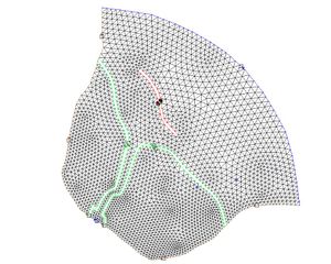
An ADCIRC weir is a boundary type that are assigned to two nodestrings on an ADCIRC mesh. A weir comprises of two nodestrings next to each other with an equal amount of nodes on each nodestrings. In order to add a weir in ADCIRC, there must be two adjacent nodestrings available as shown in figures 1 and 2 below.
The number of nodes on each nodestrings must be of an equal amount or a weir cannot be assigned. See figure 3 below. Each node and it's corresponding node on the parallel nodestring will form a node pair.
Weir Options
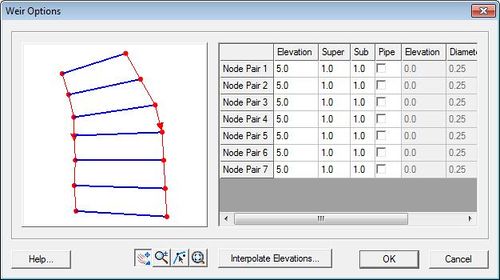
Once two nodestrings with same number of nodes exist, they can be assigned as a weir by selecting both weirs and selecting Assign BC. The Nodestring attributes will open. By selecting Weir and then clicking on the Parameters button, the Weir Options dialog will open. The dialog shows the different Node pairs and elevation for each node pair.
Elevation
Elevation of each node pair. The elevation for each node pair can be entered manually or can be interpolated from a dataset
Super
Weir flow coefficients for super critical flow. A typical value for this is 1.0.
Sub
Weir flow coefficients for sub critical flow. A typical value for this is 1.0.
- Pipe
- Elevation = elevation of the pipe
- Diameter = diameter of pipe
- Coefficient = f (L/D)
- where
- – L is the length of the pipe
- – D is the hydraulic diameter of the pipe (for a pipe of circular section, this equals to the internal diameter of the pipe)
- – f is a dimensionless coefficient called the Darcy friction factor. It can be found from a Moody diagram or by solving the Colebrook equation.
Interpolate Elevations Button
Clicking on the Interpolate Elevations button opens the XY Series Editor. The XY Series Editor can be used to generate and edit curves defined by a list of x and y coordinates. The curve can be created and edited by directly editing the xy coordinates using a spreadsheet list of the coordinates. An entire list of curves can be generated and edited with the editor and curves can be imported from and exported to text files for future use. It is also possible to paste the xy data directly to the spreadsheet.
Extract Elevations
Data entered in as a weir or island barrier boundary condition for ADCIRC define the crest elevation between the nodes. This elevation data is independent from the elevation of the nodes on the grid (usually it is assigned from a separate source).
SMS includes tools to incorporate these elevations into a Cartesian grid that will be used in a different model and/or a coverage. These tools are accessed by selecting the Extract Weir Elevations... command in the Nodestrings menu. This command is not available unless there is an ADCIRC mesh loaded into SMS.
The dialog includes three separate sections.
- The first section includes a toggle box to specify which weirs/barriers are to be used in the operation. If the toggle is not selected, all weir/barrier boundary conditions in the simulation are used. If it is toggled, only the weirs/barriers that are selected (or partially selected) will be used. If a single nodestring from a weir/barrier is selected, it is treated the same as if both were selected.
- The second section maps the specified weirs to arcs. SMS will create one arc for each weir/barrier, bisecting the area between the nodestrings that make up the boundary condition. The elevation of the nodes/vertices created on the arc will match the specified crest elevations for the weir/barrier. This can also determine if these arcs should be added to a new or existing coverage.
- The third section modifies the elevation of the cells in one or more Cartesian grids, if they are loaded into SMS, to correspond to the weir/barrier elevation. Adding the elevations to the grid causes the land surface to actually represent the shape of the weir/barrier. Caution should be exercised since assigning the crest elevation to the grid can cause steep slopes between the weir/barrier cells and adjacent cells.
After selecting OK in the dialog, SMS will compute elevations at the midpoint of each node pair in the BC. This is done by first interpolating between the node elevations of each pair, and then subtracting the weir/barrier elevation (which were specified in the weir or island barrier parameters) from that value.
If the coverage option is used, SMS will create arcs that represent the weirs or barriers on the specified coverage. The computed elevations will be assigned along the arc. If one or more grids are used, SMS will set the elevation values for all grid cells that lie underneath the midpoints to match the computed values.
Remove Weir
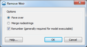
Selecting two nodestrings that have been assigned a weir boundary condition allows using the Remove Weir command in the right-click menu. Using this command will bring up the Remove Weir dialog. This dialog gives the following options for removing the weir:
- Pave over – Removes the nodestrings that had been assigned the weir boundary condition.
- Merge nodestrings – Results in new nodes down the center of where the two nodestrings used to make the weir boundary conditions.
- Runumber – Generally required for model execution. This should be done later if not done with this step.
Add Weir
Selecting a single nodestring can be used to create a weir if it is known the desired width of the weir. Right-clicking a single boundary condition nodestring and selecting the Add Weir command will bring up the Add Weir dialog. After entering the weir Width and selecting OK, the weir is created.
Related Topics
SMS – Surface-water Modeling System | ||
|---|---|---|
| Modules: | 1D Grid • Cartesian Grid • Curvilinear Grid • GIS • Map • Mesh • Particle • Quadtree • Raster • Scatter • UGrid |  |
| General Models: | 3D Structure • FVCOM • Generic • PTM | |
| Coastal Models: | ADCIRC • BOUSS-2D • CGWAVE • CMS-Flow • CMS-Wave • GenCade • STWAVE • WAM | |
| Riverine/Estuarine Models: | AdH • HEC-RAS • HYDRO AS-2D • RMA2 • RMA4 • SRH-2D • TUFLOW • TUFLOW FV | |
| Aquaveo • SMS Tutorials • SMS Workflows | ||


