SMS:ADCIRC Coverages: Difference between revisions
(→Pipes) |
|||
| Line 258: | Line 258: | ||
==Pipes== | ==Pipes== | ||
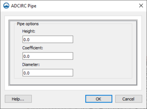
[[File:ADCIRC pipe.png|thumb|300 px|Example of the ''ADCIRC Pipe'' dialog]] | |||
Points created on this coverage can be assigned as cross barrier pipes. Right-clicking on a point and selecting the '''Assign Pipe''' command will open the ''ADCIRC Pipe'' dialog. The dialog has the following options: | Points created on this coverage can be assigned as cross barrier pipes. Right-clicking on a point and selecting the '''Assign Pipe''' command will open the ''ADCIRC Pipe'' dialog. The dialog has the following options: | ||
* ''Height'' – Cross barrier pipe height in internal barrier with cross barrier pipes. | * ''Height'' – Cross barrier pipe height in internal barrier with cross barrier pipes. | ||
Revision as of 21:20, 2 July 2019
The ADCIRC simulation can make use of different Map coverage types. The coverages specific to ADCIRC are described below.
Boundary Conditions
Much of ADCIRC's versatility as a model is due to the large number of different boundary types and boundary conditions available in the model. For detailed description of the ADCIRC boundary conditions, see the documentation provided by the ADCIRC development group at http://www.adcirc.org.
Boundary conditions are assigned by setting attributes to Feature Arcs representing boundary arcs in the domain used in the sifmulation.
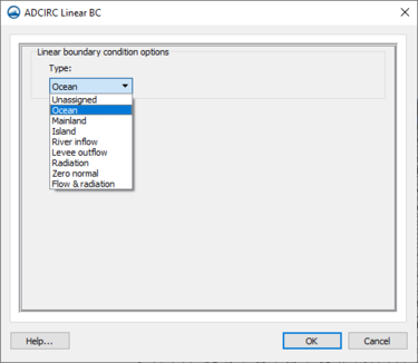
The ADCIRC Linear BC dialog defines the type of boundary conditions for each feature arc.
A feature arc/nodestring can be defined as mainland, island, normal flow, mainland barrier, island barrier, tidal constituents, etc.
To set the boundary types, choose the Select Feature Arc tool from the Toolbox and double-click the desired arc to open the ADCIRC Arc/Nodestring Attributes dialog; then assign the desired boundary conditions to the arc.
ADCIRC Boundary Types
Boundary types are assigned to feature arcs in the conceptual mode or nodestrings on the ADCIRC mesh. Correct boundary type assignments are very important to run a successful ADCIRC project. The following boundary types are available in SMS for ADCIRC:
- Unassigned – Default, no boundary condition assigned
- Ocean – This type of boundary represents an open interface for flow with a specified water surface elevation. Elevations are specified either as tidal constituents for harmonic forcing or as time series or water level.
- Mainland – This type of boundary represents a mainland boundary with no normal flow condition and free tangential slip.
- Island – This type of boundary represents an island boundary with no normal flow condition and free tangential slip. This can be selected for a closed feature arc.
- River Inflow
- Levee Outflow
- Radiation – This type of boundary represents an open boundary where waves are allowed to propagate freely out of the domain.
- Zero Normal – This type of boundary forces flow through the specified nodestring reflective of flow at a fictitious point inside the domain. This is referred to as a weakly reflective boundary in some numerical engines. The fictitious point lies on the inward directed normal to the boundary a distance equal to the distance from the boundary node to its farthest 'neighbor. This should ensure that the fictitious point does not fall into an element that contains the boundary node. The velocity at the fictitious point is determined by interpolation.
- Flow & Radiation
- Normal Flow – This type of boundary represents a river inflow or open ocean boundary with a specified normal flow condition and free tangential slip. Discharges are specified either for harmonic discharge forcing or for time series discharge forcing.
- Mainland Barrier – This type of boundary represents a mainland boundary comprised of a dike or levee. Non-zero normal flow is computed using a supercritical, free surface weir formula if the barrier is overtopped. Zero normal flow is assumed if the barrier is not overtopped.
- Island Barrier – This type of boundary represents a dike or levee that lies inside the computational domain. Non-zero normal flow is compute using either subcritical or supercritical, free surface weir formula (based on the water level on both sides of the barrier) if the barrier is overtopped. Zero normal flow is assumed if the barrier is not overtopped. This boundary condition requires two nodestrings with an equal number of nodes. See ADCIRC Weirs and Island Barriers for more information.
- Weir – This type of boundary is similar to an Island Barrier with the addition of cross barrier flow. Cross barrier flow simulates flow through the barrier simulating pipes or culverts from one side to the other. Flow rate and direction are based on barrier height, surface water elevation on both sides of the barrier, barrier coefficient and the appropriate barrier flow formula. In addition cross barrier pipe flow rate and direction are based on pipe crown height, surface water elevation on both sides of the barrier, pipe friction coefficient, pipe diameter and the appropriate pipe flow formula. This boundary condition requires two nodestrings with the same number of nodes. See ADCIRC Weirs and Island Barriers for more information.
ADCIRC Boundary Conditions Options
Depending upon the specified boundary type, the following boundary conditions are available:
| Boundary Condition | Boundary Type |
|---|---|
| Essential w/ Tangential Slip |
Mainland Island Normal Flow Mainland Barrier |
| Essential w/o Tangential Slip |
Mainland Island Normal Flow Mainland Barrier |
| Natural (w/ Tangential Slip) |
Mainland Island Normal Flow Mainland Barrier |
| Tidal Constituents | Ocean |
| Curve | Ocean |
| Extract from Dataset | Ocean |
Tidal Attributes
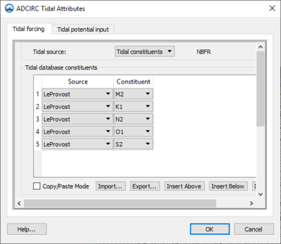
Tidal attributes can be set by going to the Project Explorer and right-clicking on the ADCRIC boundary condition coverage then selecting Tidal Attributes to open the ADCIRC Tidal Attributes dialog. This dialog contains two tabs: Tidal forcing and Tidal potential input.
Tidal forcing tab
Tidal source (NBFR) drop-down – Number of periodic forcing frequencies on elevation specified boundaries.
- "Tidal constituents"
- "Not used" – When tidal forcing is turned off, the elevation dataset input is needed to provide elevation forcing for the model. This dataset is typically a transient scatter with a limited number of points around the outside of the ocean boundary. It is not recommended to use a mesh dataset.
- Tidal database constituents section – There are two columns, and a number of options and buttons:
- Source – Contains a drop-down with the following options:
- "ADCIRC – NW Atlantic"
- "ADCIRC – NE Pacific"
- "LeProvost"
- Constituent drop-down – Has the following options:
Constituents
- "M2"
- "S2"
- "N2"
- "K1"
- "M4"
- "O1"
- "NU2" – Only available when "LeProvost" is selected in the Source column.
- "MU2" – Only available when "LeProvost" is selected in the Source column.
- "2N2" – Only available when "LeProvost" is selected in the Source column.
- "M6" – Not available when "LeProvost" is selected in the Source column.
- "Q1"
- "T2" – Only available when "LeProvost" is selected in the Source column.
- "P1" – Only available when "LeProvost" is selected in the Source column.
- "L2" – Only available when "LeProvost" is selected in the Source column.
- "K2"
- Below the edit fields are a number of options:
- Copy/Paste Mode – Allows data from an external spreadsheet to be pasted into the spreadsheet in this dialog.
- Import... – Imports tab-separated values (TSV, TXT) or comma-separated values (CSV, TXT) into the spreadsheet.
- Export... – Exports the spreadsheet data as a tab-separated value (TSV, TXT) or comma-separated value (CSV, TXT) file.
- Insert Above – Inserts a row above the selected row in the spreadsheet. If no rows exist, a single new row will be added.
- Insert Below – Inserts a row below the selected row in the spreadsheet. If no rows exist, a single new row will be added.
- Delete – Deletes the selected row in the spreadsheet.
User specified constituents section – There are seven columns:
- Amplitude – Clicking (none selected) brings up the Select Database dialog.
- Phase' – Clicking (none selected) brings up the Select Database dialog.
- Constituent drop-down – Has the following options:
Constituents
- "M2"
- "S2"
- "N2"
- "K1"
- "M4"
- "O1"
- "NU2" – Only available when "LeProvost" is selected in the Source column.
- "MU2" – Only available when "LeProvost" is selected in the Source column.
- "2N2" – Only available when "LeProvost" is selected in the Source column.
- "M6" – Not available when "LeProvost" is selected in the Source column.
- "Q1"
- "T2" – Only available when "LeProvost" is selected in the Source column.
- "P1" – Only available when "LeProvost" is selected in the Source column.
- "L2" – Only available when "LeProvost" is selected in the Source column.
- "K2"
- "User specified" – Allows the remaining four columns in this section to be edited.
- Name – Only editable if "User specified" selected from the drop-down in the Constituent column. The name of the constituent.
- Frequency – Only editable if "User specified" selected from the drop-down in the Constituent column. The frequency of the constituent.
- Nodal Factor – Only editable if "User specified" selected from the drop-down in the Constituent column. The nodal factor for the constituent.
- Equilibrium Argument – Only editable if "User specified" selected from the drop-down in the Constituent column. The equilibrium argument for the constituent.
- Below the edit fields are a number of options:
- Copy/Paste Mode – Allows data from an external spreadsheet to be pasted into the spreadsheet in this dialog.
- Import... – Imports tab-separated values (TSV, TXT) or comma-separated values (CSV, TXT) into the spreadsheet.
- Export... – Exports the spreadsheet data as a tab-separated value (TSV, TXT) or comma-separated value (CSV, TXT) file.
- Insert Above – Inserts a row above the selected row in the spreadsheet. If no rows exist, a single new row will be added.
- Insert Below – Inserts a row below the selected row in the spreadsheet. If no rows exist, a single new row will be added.
- Delete – Deletes the selected row in the spreadsheet.
Tidal potential input tab
Tidal potential (NTIP) drop-down – parameter controlling whether tidal potential and self attraction/load tide forcings will be used to force ADCIRC.
- "Not used" – Tidal potential and self attraction/load tide forcings are not used.
- "Used" – Tidal potential forcing is used. Makes the Tidal potential constituents section visible.
"Tidal potential constituents" section – There are eight columns, and a number of options and buttons:
- Source – Contains a drop-down with the following options:
- "ADCIRC – NW Atlantic"
- "ADCIRC – NE Pacific"
- "LeProvost"
- "User defined"
- Constituent drop-down – Has the following options:
Constituents
- "M2"
- "S2"
- "N2"
- "K1"
- "M4"
- "O1"
- "NU2" – Only available when "LeProvost" is selected in the Source column.
- "MU2" – Only available when "LeProvost" is selected in the Source column.
- "2N2" – Only available when "LeProvost" is selected in the Source column.
- "M6" – Not available when "LeProvost" is selected in the Source column.
- "Q1"
- "T2" – Only available when "LeProvost" is selected in the Source column.
- "P1" – Only available when "LeProvost" is selected in the Source column.
- "L2" – Only available when "LeProvost" is selected in the Source column.
- "K2"
- Constituent Name – An alphanumeric descriptor of the constituent.
- Amplitude (TPK) – Tidal potential amplitude.
- Frequency (AMIGT)
- Earth Tide Reduction Factor (ETRF) – Earth tide potential reduction factor (generally taken to be "0.690" for all constituents, but—for more precise calculations—can take on slightly different values.
- Nodal Factor (FFT) – Nodal factor argument in degrees.
- Equilibrium (FACET) – Equilibrium argument in degrees.
- Below the edit fields are a number of options:
- Copy/Paste Mode – Allows data from an external spreadsheet to be pasted into the spreadsheet in this dialog.
- Import... – Imports tab-separated values (TSV, TXT) or comma-separated values (CSV, TXT) into the spreadsheet.
- Export... – Exports the spreadsheet data as a tab-separated value (TSV, TXT) or comma-separated value (CSV, TXT) file.
- Insert Above – Inserts a row above the selected row in the spreadsheet. If no rows exist, a single new row will be added.
- Insert Below – Inserts a row below the selected row in the spreadsheet. If no rows exist, a single new row will be added.
- Delete – Deletes the selected row in the spreadsheet.
- "Self attraction/earth load tide forcing file" – Makes the Tidal potential constituents section visible.
"Tidal potential constituents" section – There are eight columns, and a number of options and buttons:
- Source – Contains a drop-down with the following options:
- "ADCIRC – NW Atlantic"
- "ADCIRC – NE Pacific"
- "LeProvost"
- Constituent drop-down – Has the following options:
Constituents
- "M2"
- "S2"
- "N2"
- "K1"
- "M4"
- "O1"
- "NU2" – Only available when "LeProvost" is selected in the Source column.
- "MU2" – Only available when "LeProvost" is selected in the Source column.
- "2N2" – Only available when "LeProvost" is selected in the Source column.
- "M6" – Not available when "LeProvost" is selected in the Source column.
- "Q1"
- "T2" – Only available when "LeProvost" is selected in the Source column.
- "P1" – Only available when "LeProvost" is selected in the Source column.
- "L2" – Only available when "LeProvost" is selected in the Source column.
- "K2"
- Constituent Name – Not editable here.
- Amplitude (TPK) – Not editable here.
- Frequency (AMIGT) – Not editable here.
- Earth Tide Reduction Factor (ETRF) – Not editable here.
- Nodal Factor (FFT) – Not editable here.
- Equilibrium (FACET) – Not editable here.
- Below the edit fields are a number of options:
- Copy/Paste Mode – Allows data from an external spreadsheet to be pasted into the spreadsheet in this dialog.
- Import... – Imports tab-separated values (TSV, TXT) or comma-separated values (CSV, TXT) into the spreadsheet.
- Export... – Exports the spreadsheet data as a tab-separated value (TSV, TXT) or comma-separated value (CSV, TXT) file.
- Insert Above – Inserts a row above the selected row in the spreadsheet. If no rows exist, a single new row will be added.
- Insert Below – Inserts a row below the selected row in the spreadsheet. If no rows exist, a single new row will be added.
- Delete – Deletes the selected row in the spreadsheet.
Flow Attributes
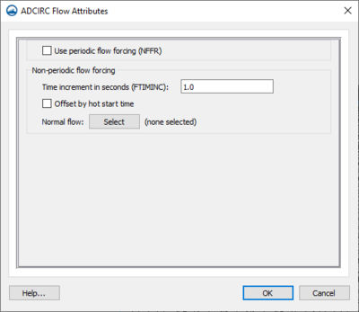
Flow attributes can be set by going to the Project Explorer and right-clicking on the ADCRIC boundary condition coverage, then selecting Flow Attributes to open the ADCIRC Flow Attributes dialog.
The first section has a single option: Use periodic flow forcing (NFFR). This is the number of frequencies in the specified normal flow external boundary condition. It is either on or off. When turned on, a Periodic flow forcing spreadsheet appears with the following columns:
- Flow Amplitude – Clicking on the (none selected) button brings up the Select Dataset dialog where a dataset can be selected.
- Flow Phase – Clicking on the (none selected) button brings up the Select Dataset dialog where a dataset can be selected.
- Name – Enter an alphanumeric descriptor of the forcing frequency.
- Frequency – A user-defined frequency of occurrence for the constituent. Must be an integer.
- Nodal Factor – A user-defined nodal factor for the constituent. Must be an integer.
- Equilibrium Argument – A user-defined equilibrium argument for the constituent. Must be degrees expressed as a decimal numeric value.
At the bottom of the spreadsheet are the following options and buttons:
- Copy/Paste Mode – Allows data from an external spreadsheet to be pasted into the spreadsheet in this dialog.
- Import... – Imports tab-separated values (TSV, TXT) or comma-separated values (CSV, TXT) into the spreadsheet.
- Export... – Exports the spreadsheet data as a tab-separated value (TSV, TXT) or comma-separated value (CSV, TXT) file.
- Insert Above – Inserts a row above the selected row in the spreadsheet. If no rows exist, a single new row will be added.
- Insert Below – Inserts a row below the selected row in the spreadsheet. If no rows exist, a single new row will be added.
- Delete – Deletes the selected row in the spreadsheet.
If Use periodic flow forcing is turned off, a Non-periodic flow forcing section is visible. It has the following options:
- Time increment in seconds (FTIMINC) – time increment (secs) between consecutive sets of normal flow boundary condition values.
- Offset by hot start time – Can be turned on or left off (default).
- Normal flow – Click the Select button to bring up the Select Dataset dialog where a dataset can be selected.
Recording Stations
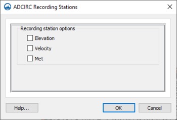
The SMS interface allows creating recording stations at specified nodal locations. At these locations, the ADCIRC model will output specified quantities at a user specified time interface. This allows for comparison of time series with observed buoy data. For example, the global output interval may be 30 minutes or 1 hour, while the recording station output could be at a higher frequency such as 6 minutes.
The following recording stations can be assigned to an ADCIRC mesh node:
2D station options include:
- Elevation – ADCIRC will output a times series of computed water surface elevation at this location.
- Velocity – ADCIRC will output a times series of computed velocity magnitude at this location.
- Concentration – ADCIRC will output a times series of constituent concentration at this location.
- Meteorological – ADCIRC will output a times series of wind and pressure variables at this location.
Pipes
Points created on this coverage can be assigned as cross barrier pipes. Right-clicking on a point and selecting the Assign Pipe command will open the ADCIRC Pipe dialog. The dialog has the following options:
- Height – Cross barrier pipe height in internal barrier with cross barrier pipes.
- Coefficient – The bulk pipe friction factor for the internal barrier boundary cross barrier pipe boundary node pair. This bulk friction factor is defined as: PIPECOEFR = fL/D where f is the classical pipe friction coefficient, L is the length of the pipe through the barrier (in consistent units) and D is the diameter of the cross barrier pipe (in consistent units).
- Diameter – Cross barrier pipe diameter in internal barrier with cross barrier pipes (diameter in units consistent with the mesh).
Wind Stations
Right-clicking on a point and selecting the Assign Wind Station command will open the ADCIRC Wind Stations dialog. The dialog has the following options:
- Wind velocity in X
- Wind velocity in y
- Pressure
SMS – Surface-water Modeling System | ||
|---|---|---|
| Modules: | 1D Grid • Cartesian Grid • Curvilinear Grid • GIS • Map • Mesh • Particle • Quadtree • Raster • Scatter • UGrid |  |
| General Models: | 3D Structure • FVCOM • Generic • PTM | |
| Coastal Models: | ADCIRC • BOUSS-2D • CGWAVE • CMS-Flow • CMS-Wave • GenCade • STWAVE • WAM | |
| Riverine/Estuarine Models: | AdH • HEC-RAS • HYDRO AS-2D • RMA2 • RMA4 • SRH-2D • TUFLOW • TUFLOW FV | |
| Aquaveo • SMS Tutorials • SMS Workflows | ||
