SMS:Feature Stamping
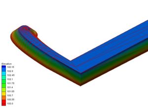
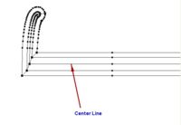
Feature stamping is the terminology used to refer to the insertion of man made structures into a natural topography or bathymetry set. In common terms, this means adding an embankment (such as a levy) or dredging a channel. A stamped feature usually follows a linear object or centerline. However, it can also be based around a single point to create a mound or pit, or applied to only one side of a closed line (a polygon) to create a flat topped mound or flat bottomed pit.
The Process
The basic steps to define a linear stamped feature include:
- Define the stamping coverage and centerline (or focal point) of the stamped feature
- Assign attributes to the centerline including
- The elevation along the centerline
- The cross sections along the centerline
- Stamp the feature. This converts the centerline and its attributes to:
- Another coverage containing all the extents and details of the feature
- A scatter set defining the elevation for the feature.
Sample problems in the section below illustrate the procedure.
Define the Coverage and Centerline
SMS utilizes a coverage of type "Stamping" to create the stamped features. Depending on the application, you may want to have multiple "Stamping" coverages to represent different design alternatives. Each coverage may contain multiple features. Create a "Stamping" coverage by right-clicking on the "Map Data" entry in the Project Explorer and selecting the New Coverage command. Then right-click on the new coverage and set its type to "Stamping".
The ambient geometry is defined by a scatter set (and one of its associated datasets). This surface determines the cut-off for the sloped banks of a stamped feature. Right-clicking on the coverage and selecting "Properties" brings up the dialog that associates a specific dataset to the stamping coverage. You must also specify whether this surface is defined as elevations (positive up) or depths (positive down). By default, SMS interprets this surface as elevation data.
Define Feature Attributes
Any arc or point created in a "Stamping" coverage has attributes to create a stamped feature. Attributes are assigned in the Stamping Point Attributes Dialog or Stamping Arc Attributes Dialog. Attributes include:
- A feature name. This will be used when SMS creates stamped feature coverages and scatter sets from the stamping coverage.
- The feature type (cut = channel or fill = embankment). If you have a stamped feature that contains both cut and fill sections, create one coverage as a cut, then duplicate the coverage and change the copies type to fill.
- A base elevation (the top elevation of the embankment or the bottom of the channel). This can be specified from the node/vertex elevations, as a constant, or extracted from a curve of elevation -vs- distance.
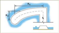
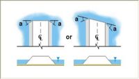
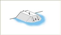
- The cross sectional shape(s). The cross section can be defined as a template, which is propagated all along an arc, or can be individually specified at each vertex in an arc. The cross section can also be defined individually for the left and right side of the arc. One point on each side of the cross section can be specified as the "shoulder". For a channel, this would be the "toe", but the reference in SMS is the shoulder point. When the arcs representing the shoulder are created, the user has the option to create an arc along this shoulder. If vertical walled structures are desired, the cross section can simply stop at the edge (shoulder). This will result in a feature arc at the edge and a scatter set for the top of the structure.
- The method for treating the ends of the structure. The options include:
- Wingwalls
- A sloped abutment (spillthrough)
- A guidebank
Stamping the Feature
To create the stamped feature, right-click on the "Stamping" coverage and select "Convert → Stamp Features ...". This brings up a dialog that allows the user to specify what output should be created from the process. Specifically, the process can create:
- A new scatter set which defines the elevation points for the new structure. This is named based on the stamped feature name. SMS triangulates all these points to create a surface and trims the scatter set to the extents of the stamped feature. The arcs that make up the stamped feature are converted to scatter breaklines to assist in the triangulation.
- A new coverage which defines the breaks and extents of the new coverage. The dialog allows the user to specify the type of the coverage. Generally, it is recommended that the coverage type be selected to match the numeric engine that will evenutally be used for the simulation. Options also exist to determine whether the stamped feature will include the center line, the shoulders, and the cross sections. The extents of the stamped feature are always generated.
Case Studies / Sample Problems
There are a wide variety of stamped features that can be created using this tool. The Feature Stamping tutorial in the general section of the tutorials may be helpful for learning to use them.
- Embankments on a flat plain
- Vertical sides on an embankment
- Sloped sides on an embankment
External Links
- Emery, R. N. (2005). Refining and Expanding the Feature Stamping Process. Thesis, Brigham Young University. [1]
- Christensen, J. R. (2001). Stamped Features: Automatic Generation of Flow Modifying Structures in Conceptual Models. Thesis, Brigham Young University.
- Zundel, Alan K. and J. Ryan Christensen, “Stamped Features: Creation of Engineered Structures in Conceptual Models”, International Journal of Hyrdroinformatics, Vol. 4, No. 1, February 2002, pp. 63-72.
SMS – Surface-water Modeling System | ||
|---|---|---|
| Modules: | 1D Grid • Cartesian Grid • Curvilinear Grid • GIS • Map • Mesh • Particle • Quadtree • Raster • Scatter • UGrid |  |
| General Models: | 3D Structure • FVCOM • Generic • PTM | |
| Coastal Models: | ADCIRC • BOUSS-2D • CGWAVE • CMS-Flow • CMS-Wave • GenCade • STWAVE • WAM | |
| Riverine/Estuarine Models: | AdH • HEC-RAS • HYDRO AS-2D • RMA2 • RMA4 • SRH-2D • TUFLOW • TUFLOW FV | |
| Aquaveo • SMS Tutorials • SMS Workflows | ||
