GMS:Horizon Conceptual Model
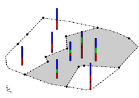
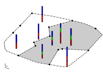
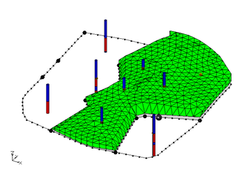
If wanting to explicitly control the areal extent of a solid created from horizons, this can be done using horizon coverages. GMS has a conceptual model type for horizons. Coverages that are inside of a horizons conceptual model can be associated with a horizon ID. The polygons in a horizon coverage determine the areal extent of the solid for the associated horizon. The first figure below shows a horizon coverage for the green material. The solid associated with this horizon will not extend beyond the boundary of the polygon. The second figure shows the solid resulting from the boreholes and the horizon coverage. When the Horizons→Solids command is executed it is possible to include a Horizons conceptual model as part of the input to the command.
The horizons algorithm is used to create either solids, HUF units, or 3D meshes from borehole and TIN data. How to use the horizon commands are explained in more detail below:
Build Horizon Coverages
The right-click menu for the horizon conceptual model contains the Build Horzon Coverages command. This command will bring up the Build Horizon Coverages wizard. All Horizon IDs must have been assigned to boreholes and there must be a coverage with a polygon before the Build Horizon Coverages wizard can be used. The wizard will offer options for which boreholes to use, which boundary coverage to use, and which horizons to generate. After running the wizard, horizons will appear as new coverages in the Project Explorer.
| GMS – Groundwater Modeling System | ||
|---|---|---|
| Modules: | 2D Grid • 2D Mesh • 2D Scatter Point • 3D Grid • 3D Mesh • 3D Scatter Point • Boreholes • GIS • Map • Solid • TINs • UGrids | |
| Models: | FEFLOW • FEMWATER • HydroGeoSphere • MODAEM • MODFLOW • MODPATH • mod-PATH3DU • MT3DMS • MT3D-USGS • PEST • PHT3D • RT3D • SEAM3D • SEAWAT • SEEP2D • T-PROGS • ZONEBUDGET | |
| Aquaveo | ||


