GMS:Horizons
The term “horizon” refers to the top of each stratigraphic unit that will be represented in a corresponding Solid, HUF unit, or 3D Mesh Layer. Horizons are numbered consecutively in the order that the strata are “deposited” (from the bottom up). Horizons can be assigned to Boreholes, TINs, and Coverages. Beginning with version 9.0, raster catalogs can also be used to define horizons.
Once horizons have been assigned to boreholes, TINs, and/or Rasters, the Horizons Wizard can be used to create solids, 3D mesh, or HUF data.
Contents
Assigning Horizons to Boreholes
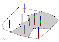
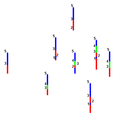
On boreholes, horizons are defined at borehole contacts. Each contact included in the construction of the solid must have a non-zero horizon ID. If wanting to ignore a contact, this can be done by leaving the horizon ID set to zero. Horizons are numbered in the order that the strata are “deposited” (from the bottom up). Gaps can exist in the horizon numbering. For example, horizons can be assigned using 1, 2, 3, etc..., or assigned horizons using 10, 20, 30, etc... . Using larger numbers with gaps can be useful if more horizons are added at a later time.
Automatic Assignment
To have GMS automatically assign horizon IDs to boreholes, use the Boreholes | Auto-Assign Horizons menu command. Depending on the number and complexity of the boreholes, this command can take a considerable amount of time.
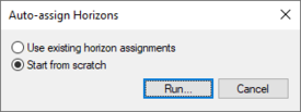
The Auto-assign Horizons dialog has two options:
- Use existing horizon assignments
- Start from scratch
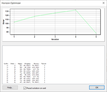
Selecting Run in the Auto-assign Horizons dialog will start the Horizon Optimizer model wrapper. With bigger and more complex sets of boreholes, the optimizer can take a significant amount of time.
Manual Assignment
Horizons are defined at borehole contacts (interface between different materials on a borehole log) by double-clicking on a contact with the Select Contact tool. The Contact horizon ID dialog is used to manually enter horizon IDs. More than one contact can be selected and assigned the same horizon ID. The Boreholes | Auto Select command can be helpful in assigning horizons to a large group of boreholes.
Assigning Horizons to TINs
A TIN horizon is assigned in the TIN Properties dialog. This dialog can be accessed by right-clicking on a TIN in the Project Explorer and selecting the properties command. Each TIN can be assigned one Horizon ID. Each TIN included in the horizons algorithm must have a horizon ID. If wanting to ignore a TIN, this can be done by setting the horizon ID to zero.
Assigning Horizons to Rasters
Raster can also be used to define horizons. See the Raster Catalog page for more information on using rasters with horizons.
| GMS – Groundwater Modeling System | ||
|---|---|---|
| Modules: | 2D Grid • 2D Mesh • 2D Scatter Point • 3D Grid • 3D Mesh • 3D Scatter Point • Boreholes • GIS • Map • Solid • TINs • UGrids | |
| Models: | FEFLOW • FEMWATER • HydroGeoSphere • MODAEM • MODFLOW • MODPATH • mod-PATH3DU • MT3DMS • MT3D-USGS • PEST • PHT3D • RT3D • SEAM3D • SEAWAT • SEEP2D • T-PROGS • ZONEBUDGET | |
| Aquaveo | ||


