GMS:Map to Models
To make modeling easier, GMS provides commands to directly convert a map module to certain models.
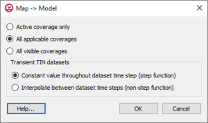
Map to Model Dialog
The Map → Model dialog provides a few options for how feature objects in Map module will be converted.
- Active coverage only – Only feature objects in the current active coverage will be converted to the model.
- All applicable coverages – GMS will examine coverages and convert only feature objects that can be used by the current active model. Coverages with attributes and feature objects that cannot be used by the active model will be ignored.
- All visible coverages – All feature objects in coverages that are displayed in the Graphics Window will be converted to the active model.
- Constant value throughout dataset time step (step function)
- Interpolate between dataset time steps (non-step function)
Map to MODFLOW
See Map to MODFLOW
Map to FEMWATER
Once the 3D mesh is constructed, the final step in converting the FEMWATER conceptual model to a mesh-based numerical model is to select the Map → FEMWATER command in the Feature Objects menu. This command assigns the wells, boundary conditions, and recharge zones assigned to the points, arcs, and polygons in the conceptual model to the nodes and element faces of the 3D mesh. At this point, the basic analysis options (steady state vs. transient, output control, material properties, etc.) must still be assigned using the tools in the FEMWATER menu. Once these basic options have been assigned, the model can be saved and FEMWATER can be launched.
Map to MT3DMS
After the conceptual model is constructed, the Map → MT3DMS command can be used to convert the conceptual model to an MT3DMS numerical model. Before the Map → MT3DMS command can be selected, the MT3DMS data must be initialized. The MT3DMS data are initialized with the following steps
- Switch to the 3D Grid module
- Select the New Simulation command from the MT3DMS menu.
- Open the Basic Transport Package dialog and set up the stress periods to use in the simulation.
Once the MT3DMS data are initialized, the Map → MT3DMS command becomes undimmed and can be selected.
Because MT3DMS already assumes a default concentration of zero for an unspecified point source sink, GMS does not create a source/sink if the concentration for the feature object has been specified as a constant value of zero.
Related Topics
| [hide]GMS – Groundwater Modeling System | ||
|---|---|---|
| Modules: | 2D Grid • 2D Mesh • 2D Scatter Point • 3D Grid • 3D Mesh • 3D Scatter Point • Boreholes • GIS • Map • Solid • TINs • UGrids | |
| Models: | FEFLOW • FEMWATER • HydroGeoSphere • MODAEM • MODFLOW • MODPATH • mod-PATH3DU • MT3DMS • MT3D-USGS • PEST • PHT3D • RT3D • SEAM3D • SEAWAT • SEEP2D • T-PROGS • ZONEBUDGET | |
| Aquaveo | ||

