GMS:Clean Command
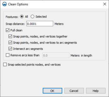
The Clean Options dialog can be accessed by clicking the Clean ![]() macro or the Feature Objects | Clean... menu command.
macro or the Feature Objects | Clean... menu command.
The dialog has several options for cleaning feature objects on a map coverage.
- Features – Determines which features will have clean operations applied to them.
- All – Every feature in the coverage will be considered by the cleaner, regardless of whether the feature is selected or not.
- Selected – Only features that are currently selected will be considered. Any unselected features will be ignored by the cleaner, as if they don't exist.
- Snap distance – Indicates how close two features must be in order to snap them together. Features which are within Snap distance of each other can snap together, while those further than this distance cannot. Features are moved one at a time, so it is possible that snapping one feature will make another opportunity available, or make an existing opportunity no longer available. This is also a per-move limit. The current implementation of the cleaner allows features to move up to 5 times each, so a feature's total movement may be as far as 5 snapping distances.
- Full clean – Enables or disables all of its sub-options at once. This is the typical way of cleaning a coverage, but the sub-options can be controlled individually if desired.
- Snap points, nodes, and vertices together – Controls whether points, nodes and vertices will snap to each other.
- Snap points, nodes, and vertices to arc segments – Controls whether points, nodes and vertices will snap to arc segments.
- Intersect arc segments – Controls whether nodes will be inserted where arcs intersect.
- Remove arcs less than ___ in length – Sets a length value which the clean tool will use to remove dangling arcs that are less than the set value. Dangling arcs are arcs where exactly one
node is attached to another arc, or the arc forms a loop.
- Snap selected points, nodes, and vertices – If this option is chosen, SMS will wait for the user to choose a snap target by clicking on any point, node, or vertex, or cancel the operation by clicking away from any valid target. Once a target is chosen, all currently selected points, nodes and vertices will be snapped to it. This is equivalent to clicking and dragging each of the selected points onto the snap target, which is a more typical workflow in SMS.
The Cleaning Algorithm
The cleaning algorithm applies several clean operations to the coverage in sequence. If snapping to segments is enabled, it is possible that cleaning the coverage once will create new cleaning opportunities, so the cleaner will apply multiple iterations and check for convergence.
The cleaning process involves maintaining "sorted" lists of locations (points, nodes and vertices) and arc segments.
- Sorting
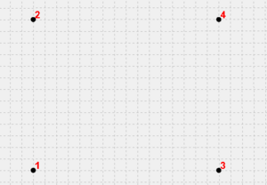
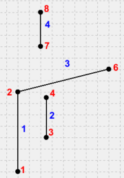
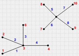
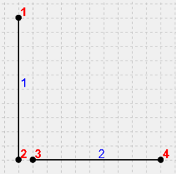
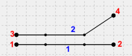
- Locations are sorted from left-to-right by their X-coordinates, with ties broken by sorting from bottom-to-top by their Y-coordinates (example 1).
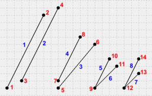
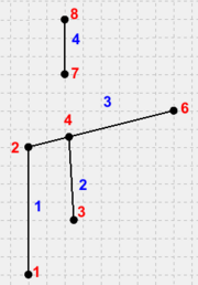
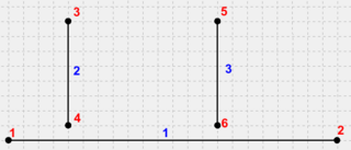
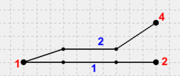
- Segments are sorted by comparing their endpoints using the same comparison as for locations. Then the "first" locations on each segment are compared, and the segment containing the earlier location is chosen first. In the event of a tie, the "second" location is used to break the tie (example 2).
- Steps
- Note that when a location is moved, it is locked in place for the remainder of the iteration.
- Vertex removal
This step is controlled by the *Snap points, nodes, and vertices together* checkbox. It always runs with the *Snap to points and nodes* and *Snap to vertices* steps. The process is to examine each segment on an arc looking for any segment that is shorter than the snap distance. If one is found, the vertex at the center of the sharpest bend is kept, and the other is removed. The first and last segments are considered last (example 3).
- Snap to points and nodes
- This step is controlled by the *Snap points, nodes, and vertices together* checkbox. It always runs with the *Vertex removal* and *Snap to vertices* steps. The process is to select the first point or node, then snap all other locations within distance to it before proceeding to the next location. This can remove some opportunities for snapping to locations by snapping a location away from where it otherwise might have gone (example 4). It can also create or remove opportunities for snapping to segments by moving segments toward or away from locations (example 5).
- The locations of points and nodes are generally more significant than those of vertices. By only considering points and nodes as snap targets, this step ensures that the location of a vertex is never favored over that of a point or node (example 6).
- Snap to vertices
- This step is controlled by the *Snap points, nodes and vertices together* checkbox. It always runs with the *Vertex removal* and *Snap to points and nodes* steps. It is identical to the Snap to points and nodes step, except that vertices are now considered as snap targets (example 6).
- Since the *Snap to points and nodes* step already snapped everything near points and nodes together, this step can only move vertices around.
- Snap to segments
- This step is controlled by the *Snap points, nodes, and vertices to arc segments* checkbox. The process is to select the first segment, then examine all other locations, in order, to find one that is within snapping distance. Once found, the nearby location will be snapped to the nearest location on the segment. The segment will also be split in two by inserting a node at the snapping point, and the two new segments will be added to the list of segments to consider (example 7).
- Note that this step only snaps to interior locations on a segment. If it finds that the closest location on the segment is actually an endpoint, then the location being considered will be skipped, even though it is within snapping distance of the segment (example 8). Snapping to endpoints is only done by the *Snap to locations* step.
- Arc intersection
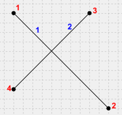
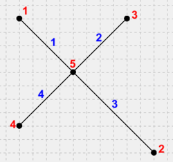
- This step is controlled by the *Intersect arc segments* checkbox. This step inserts nodes wherever two arc segments intersect (example 9). Intersection is done in an order similar to arc snapping, but since no movement happens, order is typically unimportant.
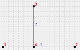
- Intersection only considers locations where two arcs cross. An arc segment may also have an endpoint on another arc segment (example 10). Since the two segments do not actually cross, intersection will not do anything with them. To clean this case, segment snapping must be enabled.
- Deduplication
- This step is always performed when any cleaning option is enabled. It removes any arcs that are duplicates of each other. When removing a duplicate arc, it preferentially removes arcs which are not part of a polygon.
- Vertex restoration
- This step is always performed when any cleaning option is enabled. It looks for cases where a vertex became a node, and attempts to convert the node back to a vertex again. See example 11.
- Remove dangling arcs
- This step is performed after all other steps are finished. Unlike the other steps, it only runs once, at the very end. It scans the coverage for any arc that is shorter than the specified length, and deletes it. If the arc was the only one attached to a node, then the node will also be removed along with it (example 12).
Examples
Note: The example images have grid lines displayed every 0.5 units. Unless otherwise noted, all examples use Mode=All, Features=All, and Distance=1. Any unspecified clean options are off.
Example 1: Point sorting
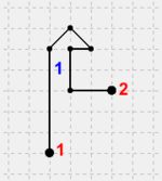
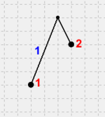
- In figure 1, Location 1 sorts before 2 because its Y-coordinate is lower, and it sorts before 3 and 4 because its X-coordinate is lower. Location 2 sorts before 3 and 4 because its X-coordinate is lower. Then 3 sorts before 4 because its Y-coordinate is lower. Location 4 is last because it has the highest X and Y coordinates.
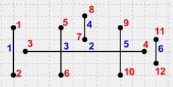
Example 2: Segment sorting
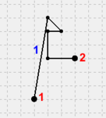
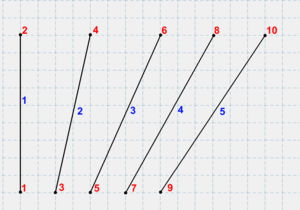
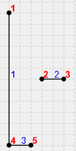
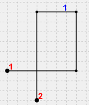
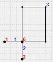
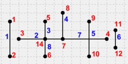
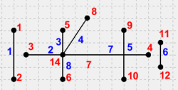
- In figure 2, location 1 is the first location on segment 1, and location 3 is the first on segment 2. The X-coordinate of location 1 is less than that of location 3, so segment 1 sorts before segment 2.
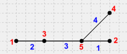
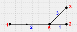
- Similarly, location 5 and 7 are the first locations on segments 3 and 4, respectively. Their X-coordinates are the same, but 5 has a lower Y-coordinate, so segment 3 sorts before segment 4.
- Segments 5 and 6 have the same first location, 9. The tie is broken by comparing locations 10 and 11. Location 10 has a lower X-coordinate, so it sorts before location 11, and its segment, 5, sorts before segment 6.
- Segments 7 and 8 are similar to 5 and 6, except that locations 13 and 14 have the same X-coordinate, so the Y-coordinate is used. This favors location 13, so segment 7 is chosen first.
Example 3: Vertex removal
- This example uses the Snap points, nodes and vertices together option.
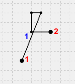
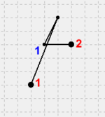
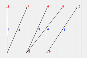
- In figure 3a, several segments are within the snap distance of 1. The arc starts from node 1 and goes to node 2, so the cleaner starts considering segments from node 1. The second segment from node 1 is too short, so it will be removed. The bend at the first vertex is 45*, while the one at the second vertex is 90*, so the first vertex is removed, giving figure 3b. The new second segment is too short. The bend at the first vertex is about 55*, while the one at the second is 45*, so the first vertex is removed and the second kept, giving figure 3c. Again, the new segment is too short. The bend at the first segment is about 68*, while the one at the second vertex is 90*, so this time the first vertex is kept and the second is removed, giving figure 3d. The middle segment is now long enough to keep. Once interior segments are removed, the first and last ones are considered. The first segment is long enough to keep, but the last is too short. Since this segment includes a node, the vertex is removed, giving figure 3e.
Example 4: Snapping locations away from locations
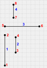
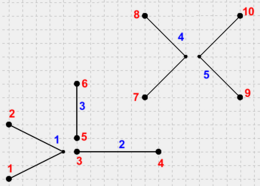
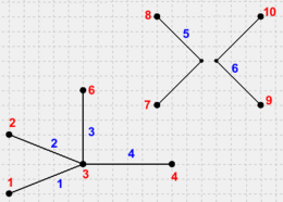
- This example uses *Snap points, nodes and vertices together*. See figure 4a. Since there are no vertices, only the *Snap to node* step is meaningful in this example. Each node is considered as a snap target, in the order shown in example 1.
- Node 1: Node 3 is nearby, so it snaps to node 1.
- Node 2: There are no locations nearby, so nothing happens.
- Node 3: Node 5 is near where node 3 started, and could have snapped in the beginning. Since node 3 already snapped to node 1, it is now too far away from node 5, so nothing snaps to it.
- Node 4: There are no locations nearby, so nothing happens.
- Node 5: Node 7 is nearby, so it snaps to node 5.
- Node 6: There are no locations nearby, so nothing happens.
- Node 7: Like nodes 3 and 5, node 9 could have snapped to node 7, but node 7 was already snapped to node 5, so the opportunity is lost.
- Node 8: There are no locations nearby, so nothing happens.
- Node 9: There are no locations nearby, so nothing happens.
- Node 10: There are no locations nearby, so nothing happens.
- The result is figure 4b.
Example 5: Snapping segments toward and away from locations
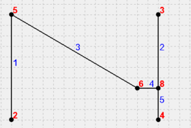
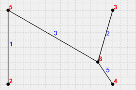
- This example uses Full clean. See figure 5a.
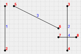
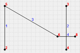
- The Snap to points and nodes step runs first. The only opportunity for location snapping is to snap node 5 to node 2, yielding figure 5b. The Snap to segments step runs next. Originally, node 7 was close enough to snap to arc 3, but snapping node 5 to node 2 moved arc 3 away from node 7, and now it is no longer in snapping range. On the other hand, node 4 was originally too far to snap to arc 3, but arc 3 moved close enough to snap after all. The result is figure 5c.
Example 6: Points and nodes are favored over vertices
- This example uses Snap points, nodes, and vertices together. See figure 6a.
- Since the vertex on arc 1 is left of node 3, it sorts before the node. However, location snapping considers points and nodes as snap targets first, so node 3 is the first snap target with nearby locations. The vertex and node 5 both snap to it, yielding figure 6b. With all the nodes snapped to, vertices are considered as snap targets next. The vertex on arc 4 sorts before the one on arc 5, and arc 5's vertex is within snapping range, so the vertex on arc 5 snaps to the one on arc 4, yielding figure 6c.
Example 7: Snapping nodes to arc segments
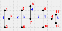
- This example uses Full clean. See figure 7a.
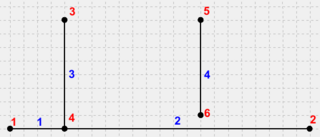
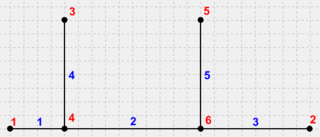
- Node 4 is snapped down to arc 1, splitting it in two and creating a new arc (figure 7b). Then node 6 is snapped down to arc 4, splitting it again and creating a new arc (figure 7c).
Example 8: Segment snapping ignores endpoints
- This example uses Snap points, nodes, and vertices to arc segments. See figure 8.
"When considering arc 1, node 3 is nearby. But the closest location to it on arc 1 is node 2, so this possibility is skipped. Similarly, when considering arc 2, node 2 is nearby. But it is closest to node 3, so this possibility is also skipped. Since the only available clean possibilities are location snaps, and location snapping is disabled, the cleaner does nothing in this case.
Example 9: Intersecting arcs
- This example uses Intersect arc segments. See figure 9a.
- The two arcs cross near the middle. The segment intersector inserts a node at the point of intersection, splitting each arc in two and yielding figure 9b.
Example 10: Intersection ignores points on segments
- This example uses Intersect arc segments. See figure 10.
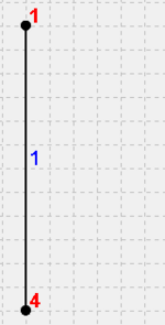
- Node 4 is exactly on arc 1, but the segment intersector ignores this case, so no change happens.
Example 11: Vertex restoration
- This example uses Snap points, nodes, and vertices together. See figure 11a.
- First, the Snap to points and nodes step snaps node 3 down to node 1 (figure 11b). Next, the Snap to vertices step snaps the two vertices on arc 2 down to the matching ones on arc 1 (figure 11c). Finally, the Vertex restoration' step attempts to restore nodes 6 and 8 to vertices. Node 6 can be restored, but node 8 is attached to 3 arcs, so it does not restore. The result is figure 11d.
Example 12: Removing dangling arcs
- This example uses Remove dangling arcs with a distance of "1". See figure 12a.
- Arc 2 has length 1, so it is removed. Since its nodes had no other arcs attached, its nodes are also removed. Arc 3 also has length 1, it is removed as well. Since node 5 had no other arcs attached, it is also removed. Node 4 is still attached to arc 1, however, so it is retained. The result is figure 12b.
Example 13: Snap to self
- This example uses Snap points, nodes, and vertices together. See figure 13a.
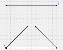
- The rightmost vertex on the narrow part of the hourglass snaps to the leftmost one, yielding figure 13b. This illustrates that an arc can potentially snap to itself.
Example 14: Self-intersection
- This example uses Intersect arc segments. See figure 14a.
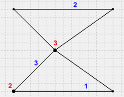
- The arc intersector inserts a node where the arc intersects itself, splitting it into three arcs and yielding figure 14b. This illustrates that an arc can potentially intersect itself.
Example 15: Multiple iterations
- This example uses Full clean. See figure 15a.
- The location snapper snaps node 5 to node 1, then node 6 to node 7, yielding figure 15b. The snapped nodes 6,7 are close enough to snap to arc 2, but snapping them locked them in place, so they remain where they are for this iteration. Node 8 is close enough to snap to arc 2, and does, yielding figure 15c. Since changes were made, another iteration begins. Now that node 8 snapped to the arc, it is close enough to be snapped to node 6, yielding figure 15d. After this iteration, cleaning converges and no more changes are made.
Example 16: Selections
- This example uses Features = Selected and Full clean. See figure 16a. Arcs 1, 2, and 3 are selected. Nodes 4 and 7 are selected.
- No locations can snap initially, so location snapping does nothing. For segment snapping, node 3 is not selected, so it does not snap to arc 1. Node 7 snaps down to arc 2, splitting it into arcs 2 and 7. Arc 6 is not selected, so node 4 does not snap to it. The result is figure 16b. During intersection, arcs 2 and 3 are selected, so an intersection is inserted there. The intersection between arcs 2 and 5 is ignored since arc 5 is not selected. The result is figure 16c. During the second iteration, the location snapping steps are able to snap node 7 to node 14, with the final result being figure 16d.
| [hide]GMS – Groundwater Modeling System | ||
|---|---|---|
| Modules: | 2D Grid • 2D Mesh • 2D Scatter Point • 3D Grid • 3D Mesh • 3D Scatter Point • Boreholes • GIS • Map • Solid • TINs • UGrids | |
| Models: | FEFLOW • FEMWATER • HydroGeoSphere • MODAEM • MODFLOW • MODPATH • mod-PATH3DU • MT3DMS • MT3D-USGS • PEST • PHT3D • RT3D • SEAM3D • SEAWAT • SEEP2D • T-PROGS • ZONEBUDGET | |
| Aquaveo | ||
