User:Jcreer/SMS:Select Intersecting Objects
From XMS Wiki
Jump to navigationJump to search
If a feature polygon is defined, it is possible to select nodes or elements in the mesh module or vertices in the data module that are inside or outside of the feature polygon. To access this tool do the following:
- On a map coverage, select a polygon that defines the area to be selected.
- Select the Feature Objects | Select Intersecting Objects command.
In the dialog that appears, select the geometry that will be used for the selection.
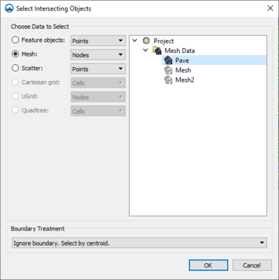
Select Intersecting Objects Dialog
The dialog contains the following options:
- Choose Data to Select – This section allows selecting specific data within the identified module where changes will eventually be applied. It contains the following options:
- Feature Objects – Enables a break down of variables within the module to which changes will eventually be applied.
- "Points" – Enables the selection of an individual, or group of specific points within the selected polygon.
- "Vertices" – Enables the selection of an angle, or angles within the selected polygon.
- "Arcs" – Enables the selection of an arc within the selected polygon.
- "Polygons" – Enables the selection of polygons within the module.
- Mesh – Enables the selection of specific components within the selected mesh from the list on the right to which the final selection will be applied.
- "Nodes" – Enables the selection of node points of the desired mesh that are inside the selected polygon.
- "Elements" – Enables the selection of specific elements of the desired mesh that are inside the selected polygon.
- "Duplicate nodes" – Enables the selection of duplicate nodes of the desired mesh that are inside the selected polygon.
- Scatter – Enables the selection of specific components within a 2D scatter module and a specific scatter set from the list on the right to establish where final changes will be applied.
- "Points" – Enables the selection of specific points within the desired scatter set that are inside the selected polygon of a 2D scatter module.
- "Triangles" – Enables the selection of a single triangle, or group of triangles within the desired scatter set that are inside the selected polygon of a 2D scatter module.
- Cartesian grid – Allows the selection of components within the desired 2D grid of a Cartesian grid module to which the final selection will be applied.
- "Cells" – Enables the selection of cells within the desired grid that are inside the selected polygon of a Cartesian grid module.
- UGrid – Enables the selection of specific components within the desired UGrid of a Ugrid module to establish where changes will eventually be made.
- "Nodes" – Enables the selection of nodes within the desired UGrid that are inside the selected polygon of a Ugrid module.
- "Cells" – Enables the selection of cells within the desired UGrid that are inside the selected polygon of a Ugrid module.
- Quadtree – Enables the selection of components in the desired quadtree of a Quadtree module to which changes will eventually be applied.
- "Cells" – Enables the selection of cells within the desired quadtree inside the selected polygon of a Quadtree module .
- Boundary Treatment
- "Ignore boundary, select by centroid." – Indicates that the components selected are outside the limitations of the boundary conditions rather they are selected by their centroid.
- "Items intersected by boundary classified as out." – Indicates that the components selected are not included if they are intersected by the boundary.
- "Items intersected by boundary classified as in." – Indicates that the components selected are included despite whether they are intersected by the boundary.
- Feature Objects – Enables a break down of variables within the module to which changes will eventually be applied.
Related Topics
| [hide] SMS – Surface-water Modeling System | ||
|---|---|---|
| Modules: | 1D Grid • Cartesian Grid • Curvilinear Grid • GIS • Map • Mesh • Particle • Quadtree • Raster • Scatter • UGrid |  |
| General Models: | 3D Structure • FVCOM • Generic • PTM | |
| Coastal Models: | ADCIRC • BOUSS-2D • CGWAVE • CMS-Flow • CMS-Wave • GenCade • STWAVE • WAM | |
| Riverine/Estuarine Models: | AdH • HEC-RAS • HYDRO AS-2D • RMA2 • RMA4 • SRH-2D • TUFLOW • TUFLOW FV | |
| Aquaveo • SMS Tutorials • SMS Workflows | ||
