|
|
| Line 4: |
Line 4: |
| ==Step 1== | | ==Step 1== |
| The first step is to define the inputs to be used, which can include [[GMS:Boreholes|boreholes]], [[GMS:TIN Module|TINs]], and a [[GMS:Horizon Conceptual Model|Horizon Conceptual model]]. | | The first step is to define the inputs to be used, which can include [[GMS:Boreholes|boreholes]], [[GMS:TIN Module|TINs]], and a [[GMS:Horizon Conceptual Model|Horizon Conceptual model]]. |
| | *''Boreholes'' – This section contains options for using boreholes. |
| | **Use boreholes |
| | **Use borehole cross sections |
| | **Representing missing horizons implicitly |
| | **Use all boreholes |
| | **Select borehole folder |
| | *''TINs'' – This section has options for using TINs. |
| | *Use horizon TINs |
| | *Use all TINs |
| | *Select TIN folder |
| | *''Raster Catalog'' – The dropdown allows selecting a [[GMS:Raster Catalog|raster catalog]] in the project. |
| | *''Conceptual model'' – This section has options for using horizon conceptual models. |
|
| |
|
| Beginning with GMS 9.0, a [[GMS:Raster Catalog|raster catalog]] can be included as input. | | <!--Beginning with GMS 9.0, a [[GMS:Raster Catalog|raster catalog]] can be included as input.--> |
|
| |
|
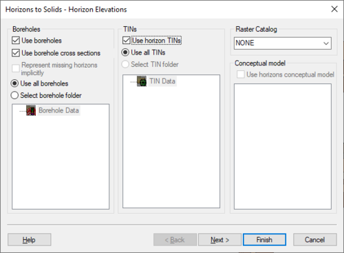
| :[[File:HorizonsWizard1.png|thumb|none|500 px|The ''Horizon Elevation'' step of the ''Horizons'' wizard]] | | :[[File:HorizonsWizard1.png|thumb|none|500 px|The ''Horizon Elevation'' step of the ''Horizons'' wizard]] |
The Horizons Wizard is used to create solids, a 3D mesh, or HUF layers from horizon data. The wizard is started via the Horizons → Solids, Horizons → 3D Mesh, Horizons → UGrid, and Horizons → HUF commands. These commands are in the TIN and Boreholes menus.
Step 1
The first step is to define the inputs to be used, which can include boreholes, TINs, and a Horizon Conceptual model.
- Boreholes – This section contains options for using boreholes.
- Use boreholes
- Use borehole cross sections
- Representing missing horizons implicitly
- Use all boreholes
- Select borehole folder
- TINs – This section has options for using TINs.
- Use horizon TINs
- Use all TINs
- Select TIN folder
- Raster Catalog – The dropdown allows selecting a raster catalog in the project.
- Conceptual model – This section has options for using horizon conceptual models.
The
Horizon Elevation step of the
Horizons wizard
Step 2
The second step is to define the top and bottom of the solid, mesh, or HUF layers. When creating HUF data, the grid elevations can be edited.
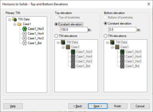
The
Top and Bottom Elevations step of the
Horizons wizard
Step 3
The third step is to define the interpolation method to be used, as well as options specific to creating solids, a mesh, or HUF package.
Beginning with GMS 7.0, when creating solids, the user can choose the option Preserve projection TIN datasets. This option will create a new TIN that will have a dataset for each horizon. This is often useful so that the user can see the result of the interpolation process for each Horizon. The user can then edit the TIN by hand and include the TIN when executing the Horizons→Solids command.
When creating a 3D mesh for a FEFLOW simulation, make sure to turn on the Prevent pinchouts (FEFLOW mesh) option. This will ensure that the mesh will contain all prism elements and that every mesh layer is continuous throughout the mesh.
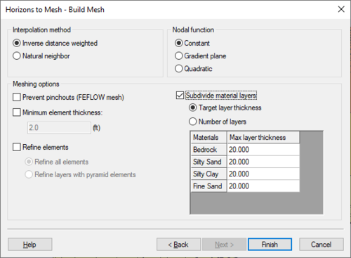
The
Build Mesh step of the
Horizons wizard


