GMS:MODPATH Particle Tracking
| MODPATH | |
|---|---|
| Pre-processing | |
| MODPATH Commands | |
| MODPATH Particle Tracking | |
| MODPATH Particle Sets | |
| MODPATH Zone Codes | |
| Post-processing | |
| MODPATH Display Options | |
| Exporting Pathlines | |
| Tutorials | |
| MODPATH Tutorials | |
Contents
Requirements
Before modeling particle tracking with MODPATH, there must be:
- A MODFLOW simulation in memory.
- A MODFLOW solution in memory computed using MODFLOW 2000 with a valid head and flow field.
If the Conceptual Model approach is used to build the MODFLOW model, the same conceptual model can be used to initialize some of the input data for MODPATH. Both the zone codes and porosities can be defined using polygons in a MODFLOW / MT3D / MODPATH Layer Attributes type coverage. The values are assigned to the cells when the Map → MODPATH command is selected.
Steps
Once there is a MODFLOW solution, all that is necessary to do particle tracking is to:
- Create particle starting locations.
As soon as the user creates the particle starting locations GMS immediately does a number of things depending on the Run MODPATH automatically for steady state models option in the MODPATH General Options dialog. If the option is on and the MODFLOW model is steady state.
Automatic Option On
- GMS saves the MODPATH input files.
- GMS launches MODPATH and passes it the input files.
- GMS waits for MODPATH to compute the pathlines.
- GMS then reads in and displays the pathlines.
All this is done automatically and behind the scenes and usually takes just a second or two. Thus, pathlines will appear almost immediately after defining the particle starting locations. If MODPATH encountered problems attempting to generate the path lines, the errors will be displayed in the MODPATH Errors dialog.
Automatic Option Off
If the Run MODPATH automatically for steady state models option is off, or the MODFLOW model is transient, save and run MODPATH manually after creating particle starting locations before pathlines will appear. This is to prevent having GMS spend lots of time updating pathlines because MODPATH can take a considerable amount of time with large, transient models. The MODPATH | Run MODPATH menu command or equivalent toolbar macro can be used to run MODPATH.
Generating Particles
There are three ways to generate particle starting locations in GMS, with two available via the MODPATH menu:
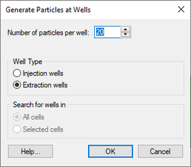
- Generate Particles at Wells – Accessed in the MODPATH menu. This command automatically generates particle starting locations in cells containing wells. The specified number of particle starting locations are distributed evenly in a horizontal circle around the center of the cells containing the wells. Specify the number of starting locations per cell, and whether the user wants starting locations created in extraction well cells, or injection well cells.
- Injection Wells – If this option is selected, particles are created in cells with wells that have a positive flow rate. The tracking direction for the current particle set is changed to forward.
- Extraction Wells – If this option is selected, particles are created in cells with wells that have a negative flow rate. The tracking direction for the current particle set is changed to backward.
- Selected Wells – This option makes it possible to generate particles at either all wells or only at wells within selected cells.
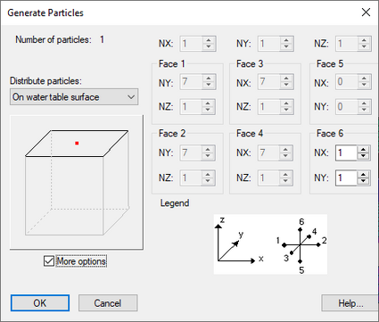
- Generate Particles at Selected Cells – Accessed in the MODPATH menu. This command opens the Generate Particles dialog, and when selecting OK, particles are created in all the selected cells according to the options specified.
- Number of Particles – If the More options toggle is not selected, the user can use the slider to change the number of particles created per cell. The minimum is 1, and the maximum depends on the option being used to distribute the particles. The number of particles jumps as the slider is moved in order to create an even distribution of particles. If the More options toggle is selected, the slider is not available, and the user has more control over the total number of particles and how they are distributed.
- Distribute Particles – There are three options for distributing the particles within the selected cells.
- "Within Cell" – With this option, the particles are distributed in the interior of the cells.
- "On Cell Faces" – With this option, the particles are distributed on the faces of the cells.
- "Distribute Starting Points on Water Table Surface" – With this option, the particles are restricted to the top face only. When using this option, be sure to select the cells corresponding to the location of the water table surface.
- "More Options" – This option expands the dialog, allowing the user to further define how particles are distributed within the selected cells.
- (These commands are only available if a MODFLOW CCF solution generated by MODFLOW 2000 exists, and 3D grid cells are selected.)
- Converting 3D Scatter Set – This option is accessed by right-clicking on a created 3D Scatter Set in the Project Explorer and clicking Convert To | MODPATH Starting Locations.
Transient MODFLOW Solution
For each time step, particle paths are computed just as for the steady state case until the end of the time step is reached. A new velocity distribution is then calculated for the next time step and the computation of particle paths is resumed. The computation of paths forward or backward, boundary conditions, and the path line termination criteria are handled the same as for steady state flow.
| [hide]GMS – Groundwater Modeling System | ||
|---|---|---|
| Modules: | 2D Grid • 2D Mesh • 2D Scatter Point • 3D Grid • 3D Mesh • 3D Scatter Point • Boreholes • GIS • Map • Solid • TINs • UGrids | |
| Models: | FEFLOW • FEMWATER • HydroGeoSphere • MODAEM • MODFLOW • MODPATH • mod-PATH3DU • MT3DMS • MT3D-USGS • PEST • PHT3D • RT3D • SEAM3D • SEAWAT • SEEP2D • T-PROGS • ZONEBUDGET | |
| Aquaveo | ||

