SMS:Arcs: Difference between revisions
No edit summary |
|||
| Line 157: | Line 157: | ||
==Prune Arc== | ==Prune Arc== | ||
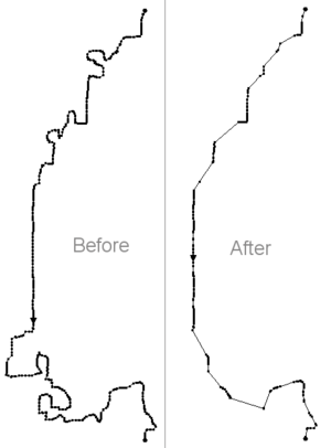
[[File:PruneArcExample.png|thumb|300 px|Arc before pruning and arc after pruning]] | [[File:PruneArcExample.png|thumb|300 px|Arc before pruning and arc after pruning]] | ||
If two non-neighboring vertices are within a certain width of each other in such a way that a concave section of the arc is formed, then the vertices between the two vertices can be removed. This pruning smooths out the arc in the concave area without changing the distribution of vertices along the rest of the arc. | If two non-neighboring vertices are within a certain width of each other in such a way that a concave section of the arc is formed, then the vertices between the two vertices can be removed. This pruning smooths out the arc in the concave area without changing the distribution of vertices along the rest of the arc. Importantly, this tool can be used to remove concave sections along one side of the arc. | ||
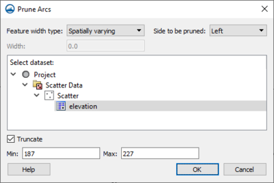
[[File:PruneArcs.png|thumb|none|400 px|Example of the ''Prune Arcs'' dialog]] | [[File:PruneArcs.png|thumb|none|400 px|Example of the ''Prune Arcs'' dialog]] | ||
To prune an arc, right-click on the selected arc and select the '''Prune Arc(s)''' command. The ''Prune Arcs'' dialog has the following options: | To prune an arc, right-click on the selected arc and select the '''Prune Arc(s)''' command. The ''Prune Arcs'' dialog has the following options: | ||
Revision as of 15:56, 28 October 2019
SMS has many utilities that can be used to modify feature arcs. Most of these can be accessed by selecting and right-clicking on the arcs that are to be operated on.
Delete
This command deletes the selected arcs. SMS will prompt to confirm that the deletion is desired if the Confirm Deletions option is enabled in the SMS Preferences.
Show Observation Plot
This command is a shortcut to create an observation plot for the selected arc(s). The plot will use the selected arcs and generate a curve for the active dataset in the active mesh if one exists. If a mesh does not exist the plot will use the active dataset in the active scatter set if that exists.
Split Feature Arc
Arcs are used to represent features in a conceptual model. A feature arc may represent a very small (short) individual feature, or it may represent a convoluted complex feature such as an entire shoreline. Two sample applications include arcs representing a shoreline, or arcs representing the thalweg of a river. There are advantages to having a single arc represent a long feature. These include the ability to select the entire feature easily, it is less cumbersome to manage the feature because there are less features, and to ensure that there are no gaps in the feature because it is a single arc. However, there are also applications and purposes for splitting the arc into pieces. One such example is illustrated by the change of shape an arc undergoes when it is redistributed. The vertices move, but the feature nodes do not. In this situation, making key points nodes prevents the arcs shape from loosing its ability to represent these key locations. In the case of a thalweg, it could be advantageous to have a separate arc for each section of the river. Each arc would then span from one river station to another (perhaps every 100 yards or meters, or each river mile).
This utility is in the right-click menu when selecting one or more arcs. The command brings up the Split Arcs Tool dialog. In this dialog provide criterion for splitting the selected arc(s) into multiple arcs. If desiring to process all the arcs in a coverage, use Select All first.
There dialog includes three toggle boxes associated with criteria including:
- Split long arcs – If this is selected, specify a length (labeled as ft or m) based on the current projection. Processed arcs will be split into arcs of this specified length starting at the first of the arc. The last arc in the group will generally not be the specified length.
- Split sharp corners – If this is selected, specify an angle (labeled as degrees). This is the angle of deviation from one arc segment to the next. A straight line has an angle of deviation of 0.0. If the arc doubled back on itself completely, the angle of deviation is 180 degrees. This deviation is a magnitude. A left turn is processed identically to a right turn. Processed arcs will be split at vertices where the arc direction changes more than the specified angle.
- Split long segments – If this is selected, specify a threshold length. If a segment is longer than this threshold, the vertices at either end will be converted to nodes making it a separate arc.
If multiple toggles are selected, the arc will first be split based on maximum arc length, the resulting arcs will be split based on angle, and finally the resulting arcs will be processed for long segments. This will retain the feature of creating feature nodes at the key length locations, and then add additional feature nodes at bends.
Offset Arc
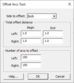
The offset arc command (arc right-click) provides a mechanism to create additional arcs in a coverage by offsetting from the selected arc(s). Multiple offsets can be created in a single command. This command brings up a dialog that asks for a number of parameters including:
- The direction of the offset (to the left of the arc, to the right of the arc or both).
- The number of arcs to create in the specified direction.
- The maximum offset in the specified direction. If more than one offset is created on a side, the offset provided is for the last offset and the others are interpolated between the original arc and the specified offset. (If to arcs are created on the left side with an offset of 10.0, the first is offset by 5 and the second is offset by 10.)
This command uses the orientation of the selected arc as a basis meaning it knows one end of the arc as the "start" and the other as the "end". This convention is determined based on the creation of the arc. This direction is not always obvious, so it may be necessary to investigate using trial and error which end is the start and which end is the end (as with bias in the redistribute command).
This command has several useful applications. These include:
- When defining a conceptual model, the base line data may include a feature such as a thalweg or a toe of a bank, or a center-line of a road or levee. The offset arc command can be used to approximate the opposing bank, a shoulder from a toe or similar, nearly parallel feature.
- When creating arcs that define a tropical storm path, variations of that path may be desired. The offset arc command creates arcs to represent these paths.
Align Arc With Contour
This command (arc right-click) can only be used when the project has scatter data. A dialog is brought up from which a scatter dataset, dataset value, and maximum distance are set. SMS will then move the vertices along the selected arc to locations where the scatter dataset value matches the dataset value specified in the dialog, as long as it is not moved by a distance greater than the maximum distance (also specified in the dialog). This is done by processing each location individually. For each point, SMS extracts the contour value from the TIN/dataset and the gradient of the TIN at the (x,y) location. It then tracks up or down gradient to intersect with the contour at the specified dataset value. If a local extrema is encountered before finding the contour, the operation fails.
Redistribute Vertices
The primary function of the vertices of an arc is to define the geometry of the arc. If the arcs are to be used for automatic mesh generation, the spacing of the vertices is important. The spacing of the vertices defines the density of the elements in the resulting mesh. Each edge defined by a pair of vertices becomes the edge of an element. The mesh gradation is controlled by defining closely spaced vertices in regions where the mesh is to be dense and widely spaced vertices in regions where the mesh is to be coarse.
When spacing vertices along arcs, the Redistribute command in the Feature Objects menu (or using the right-click menu) can be used to automatically create a new set of vertices along a selected set of arcs at either a higher or lower density. The desired arc(s) needs to be selected prior to selecting the Redistribute command.
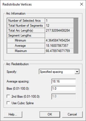
The current status of the selected arc(s) is given at the top of the dialog. This includes the number of segments and spacing of those segments. When multiple arcs are selected, the current status is a combination of all selected arcs. However, the parameters set in this dialog apply to each arc individually. Therefore if multiple arcs were selected, each arc would reflect the options selected in this dialog.
In versions of SMS prior to 13.0, vertices on an arc would be redistributed during a scalar paving operation to match the target size function if possible. This operation could be useful outside of the mesh generation process, and may not always be desired during mesh generation, so it was separated into a separate operation.
Vertices along an arc can be redistributed using a size function dataset. This options is selected in the Redistribute Vertices dialog. Once the Size Function option is set, a dataset must be assigned. Clicking the Options button will bring up dialogs that allow assigning the size function.
The following options are available for redistributing vertices:
- "Specified spacing" – Will redistribute the vertices along the applying the Average and Bias parameters to determine the distance between each vertex. The first bias will shift the spacing to add or keep more vertices at the start of the arc. The second bias will do the same for the end of the arc.
- "Number of segments" – Will create or remove vertices along the arc, as well as redistribute, based on the Number of vertices parameter. Allows setting a bias.
- "Min/max spacing" – Will have vertices closer together at the start of the arc and gradually increase the segment lengths up to the Max length parameter.
- "Source arc" – See below.
- "Size Function" – Allows using a size function dataset for redistribution.
- Use Cubic Spline – Option for spline interpolation.
Linear Interpolation
If the Linear interpolation options is specified, then either a number of intervals or a target spacing can be given to determine how points are redistributed along the selected arcs. In either case, the new vertices are positioned along a linear interpolation of the original arc. The arc may change shape due to the fact that original vertices are removed as the new vertices are created. This may round corners from the arc.
Spline Interpolation
If the Use Cubic Spline option is specified, vertices are redistributed along a series of cubic splines defined by the original vertices of the selected arcs. The difference between the linear and spline interpolation methods is illustrated in the figure below.
Source Arc
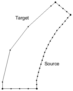
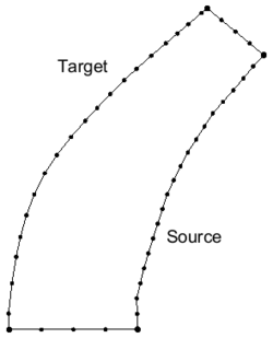
The "Source arc" option is only available when two arcs are selected. One arc is specified to be the source arc while the other is the target arc. SMS redistributes the vertices on the target arc to be as close as possible to the vertices on the source arc.
Reverse Arc Direction
This command (Feature Objects in the Map module or right-clicking on a selected arc) reverses the direction of all selected arcs. Arc orientation is only important for applications that use coastline or centerline arcs that have an arrow drawn on the arc.
Each arc has a direction. One node is the "from" node, the other node is the "to" node. For most applications, the direction of the arc does not matter. However, when the arc is used to define a observation plots, and in various other situations the direction of the arc becomes significant. The Reverse Arc Direction command can be used to change the direction (upstream to downstream) for an arc.
Smooth Arc
This command reduces the variability or roughness of an arc. When an arc is created by digitization, it includes the manual variations and noise from the digitization process. Similarly, when an arc is created to follow a contour line, it can have numerically created corners and bends. Smoothing an arc results in more gradual bends in the shape of the arc. Applying the smooth command repetitively will eventually result in a straight line.
An arc should not be smoothed, if the meanders and bends accurately depict a physical feature. However, smoothing may result in more gradual variations that can enhance numerical stability.
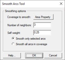
When the Smooth Arc command is used, the dialog that appears asks to specify the number of neighbors to be included in the smoothing window and a self weight. As the number of neighbors increases and the self weight decreases, the level of smoothing becomes more dramatic (moves to a straight line more quickly).
The algorithm computes a new position for each vertex in the arc from the existing vertex positions. The number of neighbors must be the same both before the vertex being smoothed and after. Since there are no vertices before the first node, and none after the last node, these two locations are not impacted by the smoothing process. The first vertex can be smoothed using the first node from before its position, and the first vertex after its position.
If the self weight is set to 1.0, no influence is assigned to the neighbors, so the arc does not smooth at all. If the self weight is set to 1/3, and the number of neighbors is set to 1, then each of the points has an even 1/3 weight in determining the new vertex location. If the self weight is set to 1/5, and the number of neighbors is set to 2, then five vertices impact the new location (Two vertices before the vertex in question and two vertices after) and the resulting point is the average of those five points (20% self weight, 80% neighbor weight with four neighbors).
Transform
See the article Data Transform
Select Connected Arcs
See the article Select Connected Arcs.
Create Arc Group
The Create Arc Group command is found in the Feature Object menu of the Map module. By selecting multiple arcs and using this command, the arcs will be made into a group. When selecting any one of the arcs in the group, all arcs in the group will be selected.
Create Contour Arcs
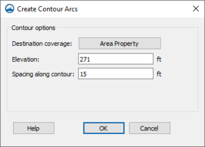
The Create Contour Arcs dialog is used to create a feature arc along a specified elevation of the active scatter dataset or cartesian grid elevation. To access the dialog do the following:
- Right-click on a Cartesian Grid or Scatter set in the Project Explorer.
- Select Convert then 2D Grid Contours→Map for Cartesian Grid, otherwise select Convert then Scatter Contours→Map. This brings up the Create Contour Arcs dialog. By default the active coverage is selected. A prompt will ask for the elevation and vertex spacing along contour.
The dialog allows specifying the following attributes:
- Destination Coverage – Clicking on this button will bring up a Select Tree Item coverage where an existing coverage can be designated to receive the contour arcs.
- Elevation – Designates an elevation level SMS will use to create the contour arcs. If the value enter does not match any of the existing elevation, no arcs will be generated.
- Spacing – Indicates the distance between vertices along the generated arcs.
Arc Attributes Dialogs
Feature Arc Attributes depend on the type of coverage being used. A purely geometric arc would have no special attributes, but arcs may be used to define specific types of features such as a coastline, open ocean boundary, stream thalweg, or edge of water. In addition, feature arcs may have model specific boundary condition definitions which should be applied to a geometric object of that model type at the location of the arc.
The Arc Attributes dialog is a dynamic dialog that will provide different options depending on the coverage type.
Recompute All Stations
This function (found in the Feature Objects menu) can be used if an arc's "Computational Length" value on a river changes. It sets the Start and End station values for each of the arcs with the same river name based on the computational lengths of each arc. So, for example, if there are 3 arcs in a river, the most downstream arc being 30 feet, the next arc being 40 feet, and the next arc being 50 feet, the starting and ending stations would be as follows for each of the arcs (Arc 1 is downstream):
Arc Start Station End Station 1 0.0 30.0 2 30.0 70 3 70.0 120.0
These start and end stations are set when assigning a river name to an arc, so there there should not be a need to use the Recompute All Stations command unless there is a change in the computational length, start station, or end station values for a centerline arc.
Filter Arc
The Filter Arcs Tool dialog is accessed through the right-click menu of a selected arc. The dialog allows filtering all arcs on a coverage. Options include:
- Coverage to filter – Selects the coverage to filter.
- Maximum arc length – Set a value for the maximum arc length. Arcs with a length under this value will be selected or deleted.
- Select filtered items – Arcs that fall below the maximum segment length will be selected.
- Delete filtered items – Arcs that fall below the maximum segment length will be deleted.
Filter Arc Segments
The Filter Arcs Segments Tool dialog is accessed through the right-click menu of a selected arc. The dialog allows filtering all arcs on a coverage. Options include:
- Coverage to filter – Selects the coverage to filter.
- Maximum segment length – Set a value for the maximum segment length. Segments with a length under this value will be selected or deleted.
- Select filtered items – Arc segments that fall below the maximum segment length will be selected.
- Delete filtered items – Arc segments that fall below the maximum segment length will be deleted.
Prune Arc
If two non-neighboring vertices are within a certain width of each other in such a way that a concave section of the arc is formed, then the vertices between the two vertices can be removed. This pruning smooths out the arc in the concave area without changing the distribution of vertices along the rest of the arc. Importantly, this tool can be used to remove concave sections along one side of the arc.
To prune an arc, right-click on the selected arc and select the Prune Arc(s) command. The Prune Arcs dialog has the following options:
- Feature width type – Select the method for pruning. Can be "Constant" or "Spatially varying".
- "Constant" – Uses a constant width is used for the entire length of the arc for determining possible concave areas.
- Width – The constant value used for pruning the arc.
- "Spatially varying" – Usees a size function to allow for different widths along the length of the arc.
- Select dataset – This table will show a tree of datasets available to use with the "Spatially varying" type. The domain of the dataset should cover the entirety of all arcs. The dataset will be linearly interpolated to each point of the arc to be used as a width to determine possible pruning. If the dataset is temporally varying, then the active time step is used.
- Truncate – If "Truncate" is checked, then the dataset values used for each point are truncated to be with Min and Max values. Min and Max are defaulted to the minimum and maximum values of the dataset at the active time step.
- "Constant" – Uses a constant width is used for the entire length of the arc for determining possible concave areas.
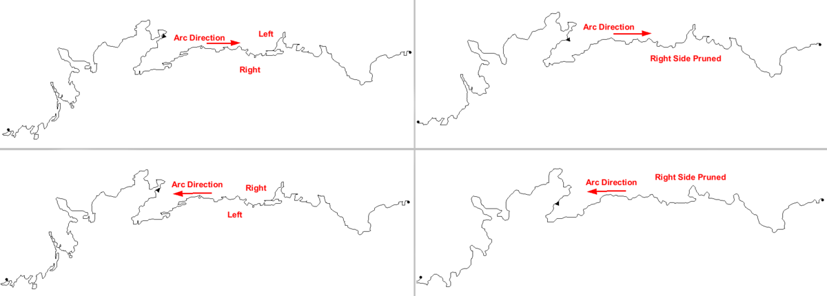
- Side to be pruned – Can be set to either "Left" or "Right". These values represent which side of the arc will be potentially pruned. "Left" and "Right" are relative to the direction of the arc.
Related Topics
| [hide] SMS – Surface-water Modeling System | ||
|---|---|---|
| Modules: | 1D Grid • Cartesian Grid • Curvilinear Grid • GIS • Map • Mesh • Particle • Quadtree • Raster • Scatter • UGrid |  |
| General Models: | 3D Structure • FVCOM • Generic • PTM | |
| Coastal Models: | ADCIRC • BOUSS-2D • CGWAVE • CMS-Flow • CMS-Wave • GenCade • STWAVE • WAM | |
| Riverine/Estuarine Models: | AdH • HEC-RAS • HYDRO AS-2D • RMA2 • RMA4 • SRH-2D • TUFLOW • TUFLOW FV | |
| Aquaveo • SMS Tutorials • SMS Workflows | ||
