WMS:Basin HEC-1 Cards: Difference between revisions
| (21 intermediate revisions by 2 users not shown) | |||
| Line 1: | Line 1: | ||
[[Image:Edit HEC-1 Parameters. | [[Image:Edit HEC-1 Parameters.png|thumb|470 px|''Edit HEC-1 Parameters'' dialog]] | ||
When a basin is selected in the HEC-1 model, selecting ''HEC-1'' | '''Edit Parameters''' will bring up the ''Edit HEC-1 Parameters'' dialog with the ''Basin HEC-1 Cards'' section active. The following can then be specified: | When a basin is selected in the HEC-1 model, selecting ''HEC-1'' | '''Edit Parameters''' will bring up the ''Edit HEC-1 Parameters'' dialog with the ''Basin HEC-1 Cards'' section active. The following can then be specified: | ||
==''HEC-1 Basin Data'' Dialog== | ==''HEC-1 Basin Data'' Dialog== | ||
| Line 6: | Line 7: | ||
Dialog is accessed by selecting ''HEC-1'' | '''Edit Parameters...''' in WMS and then choosing '''Basin Data...''' from the ''Edit HEC-1 Parameters'' dialog. | Dialog is accessed by selecting ''HEC-1'' | '''Edit Parameters...''' in WMS and then choosing '''Basin Data...''' from the ''Edit HEC-1 Parameters'' dialog. | ||
[[Image:HEC1 Basin Data. | [[Image:HEC1 Basin Data.png|Thumb|200 px|''HEC-1 Basin Data'' dialog]] | ||
''Basin name''– Each hydrograph station should be identified with a unique name. This name appears as part of the KK record for that station in the input file. | ''Basin name''– Each hydrograph station should be identified with a unique name. This name appears as part of the KK record for that station in the input file. | ||
| Line 28: | Line 29: | ||
==''HEC-1 Output Control'' Dialog== | ==''HEC-1 Output Control'' Dialog== | ||
[[Image:HEC1 Output Control. | [[Image:HEC1 Output Control.png|thumb|400 px|''HEC-1 Output Control'' dialog]] | ||
Dialog is accessed by selecting ''HEC-1'' | '''Edit Parameters...''' in WMS and then choosing '''Output Control...''' from the ''Edit HEC-1 Parameters'' dialog. | Dialog is accessed by selecting ''HEC-1'' | '''Edit Parameters...''' in WMS and then choosing '''Output Control...''' from the ''Edit HEC-1 Parameters'' dialog. | ||
| Line 57: | Line 58: | ||
==''HEC-1 Precipitation'' Dialog== | ==''HEC-1 Precipitation'' Dialog== | ||
[[Image:HEC1 Precipitation. | [[Image:HEC1 Precipitation.png|thumb|400 px|''HEC-1 Precipitation'' dialog]] | ||
Precipitation patterns are assigned to basins by first selecting the appropriate basin(s) and then clicking on the '''Precipitation''' button in the ''Edit HEC-1 Parameters'' dialog. If multiple basins are selected then the defined parameters will apply to all selected basins. | Precipitation patterns are assigned to basins by first selecting the appropriate basin(s) and then clicking on the '''Precipitation''' button in the ''Edit HEC-1 Parameters'' dialog. If multiple basins are selected then the defined parameters will apply to all selected basins. | ||
| Line 94: | Line 95: | ||
==''HEC-1 Loss Methods'' Dialog== | ==''HEC-1 Loss Methods'' Dialog== | ||
[[Image:HEC1 Loss Methods. | [[Image:HEC1 Loss Methods.png|thumb|400 px|''HEC-1 Loss Method'' dialog]] | ||
Dialog is accessed by selecting ''HEC-1''|'''Edit Parameters...''' in WMS and then choosing '''Loss Method...''' from the ''Edit HEC-1 Parameters'' dialog. | Dialog is accessed by selecting ''HEC-1''|'''Edit Parameters...''' in WMS and then choosing '''Loss Method...''' from the ''Edit HEC-1 Parameters'' dialog. | ||
''Uniform (LU)'' – Losses are used in conjunction with the uniform (LU) or exponential (LE) loss methods. | ''Uniform (LU)'' – Losses are used in conjunction with the uniform (LU) or exponential (LE) loss methods. | ||
| Line 127: | Line 127: | ||
*''RTIMP'' – Ratio of the drainage basin that is impervious. Values should be less than or equal to 1. | *''RTIMP'' – Ratio of the drainage basin that is impervious. Values should be less than or equal to 1. | ||
==Unit Hydrograph | ==''HEC-1 Unit Hydrograph Methods'' Dialog== | ||
[[Image:HEC1 Unit Hydrograph Methods. | [[Image:HEC1 Unit Hydrograph Methods.png|thumb|400 px|''HEC-1 Unit Hydrograph Methods'' dialog]] | ||
One of several different unit hydrograph methods can be chosen when generating synthetic hydrographs. A method is assigned to a basin by first selecting the basin and then choosing the '''Unit Hydrograph Method''' button from the ''Edit HEC-1 Parameters'' dialog. As with other basin options the same parameters can be assigned to several basins by selecting multiple basins before accessing the ''Unit Hydrograph Method'' dialog | One of several different unit hydrograph methods can be chosen when generating synthetic hydrographs. A method is assigned to a basin by first selecting the basin and then choosing the '''Unit Hydrograph Method''' button from the ''Edit HEC-1 Parameters'' dialog. As with other basin options, the same parameters can be assigned to several basins by selecting multiple basins before accessing the ''Unit Hydrograph Method'' dialog. | ||
Dialog is accessed by selecting ''HEC-1'' | '''Edit Parameters...''' in WMS and then choosing '''Unit Hydrograph Method...''' from the ''Edit HEC-1 Parameters'' dialog. | |||
''Clark (UC)'' – Clark Method. | |||
*''T<sub>C</sub>'' – Time of concentration in hours for the unit hydrograph. | |||
*'' | *''R:'' – The Clark storage coefficient in hours. | ||
*''Define Time Area'' – The time area curve defines the area of the watershed contributing runoff to the basin outlet as a function of time. Select to bring up the [[WMS:XY Series Editor|''XY Series Editor'' dialog]]. | |||
*'''Compute Tc and R-Maricopa County''' – This option is only available when the selection of Green ampt (LG) or Uniform (LU) Loss method in the HEC-1 Loss Methods dialog has been done. | |||
''Snyder (US)'' – Snyder unit hydrograph. | |||
*''TP:'' – Lag time in hours. | |||
*''CP:'' – Peaking coefficient. | |||
*''Define Time Area'' – The time area curve defines the area of the watershed contributing runoff to the basin outlet as a function of time. Select to bring up the [[WMS:XY Series Editor|''XY Series Editor'' dialog]]. | |||
''SCS dimensionless (UD)'' – Soil Conservation Services unit hydrograph that contains dimensionless time units and dimensionless discharge units. | |||
*''TLAG:'' – Lag measured in hours. | |||
''Given unit hydrograph (UI)'' – A given unit hydrograph determined from a separate analysis. The given unit hydrograph must be derived for the same time interval as is specified on the IT record in the ''Job Control'' dialog. | |||
*'''Define Unit Graph''' – Select to bring up the [[WMS:XY Series Editor|''XY Series Editor'' dialog]]. | |||
*'''Maricope County S-Graph''' – Select this to bring up the ''S-Graph Option'' dialog. | |||
**''S-Graph Types'' section – Section that allows the choice of areas within Maricopa County for which an S-Graph will be created. | |||
***"Phoenix Valley" – Area within Maricopa County. | |||
***"Phoenix Mountain" – Area within Maricopa County. | |||
***"Desert rangeland" – Area within Maricopa County. | |||
***"Agricultural" – Represents the agriculture of Maricopa County. | |||
*Basin area=31.8901 (sq. miles) | |||
**''Basin Lag Time:'' – Measured in minutes. | |||
**''Computational Time Step:'' – 15 minutes. | |||
''Kinematic Wave (UK)'' – Section of the dialog where you can specify the characteristics attributed to the Kinematic Wave Method. | |||
*''First Kinematic Record'' ‐ Section where the first data found regarding the Kinematic Wave Method can be recorded. | |||
**''L:'' – Represents the Overland flow length (measured in ft). | |||
**''S:'' – Representative slope (measured in ft/ft). | |||
**''N:'' – Represents Manning's roughness coefficient. | |||
**''A:'' – Represents the percentage of sub-basins area that this record represents (The total of the two records must be the sum of 100). | |||
*'''Define Loss''' – Click to open the [[#HEC-1 Loss Methods Dialog|''HEC-1 Loss Methods'' dialog]]. | |||
*''Second Kinematic Record'' – Section where the second found data regarding the Kinematic Wave Method can be recorded. | |||
**''L:'' – Represents the Overland flow length (measured in ft). | |||
**''S:'' – Representative slope (measured in ft/ft). | |||
**''N:'' – Represents Manning's roughness coefficient. | |||
**''A:'' – Represents the percentage of sub-basins area that this record represents (The total of the two records must be the sum of 100). | |||
*'''Define Loss''' – Click to open the [[#HEC-1 Loss Methods Dialog|''HEC-1 Loss Methods'' dialog]]. | |||
*''RK'' – Represents the Kinematic Wave routing. | |||
*''RD'' – Represents the Muskingum-Cunge routing. | |||
*'''Define Channels''' – Click to open the [[WMS:Basin HEC-1 Cards#RK/RD Channels Dialog|''RK/RD Channels'' dialog]]. | |||
*'''Basin Geometrical Attributes''' – Select to bring up the [[#Basin Geometric Attributes Dialog|''Basin Geometric Attributes'' dialog]] to define the geometric attributes of the data collected from the Basin. | |||
*'''Compute Parameters-Basin Data''' – Select to bring up the [[#Basin Time Computation Dialog|''Basin Time Computation'' dialog]] and compute the parameters of the basin data collected. | |||
*'''Compute Time Area Curve(s)''' – Select to bring up the ''Time Area Parameters'' dialog that allows you to specify the maximum run off distance and interval to determine the time area curve. (Option is only available when ''Snyder (US)'' is selected in the ''HEC-1 Unit Hydrograph Methods'' dialog.) | |||
*'''Compute Parameters-Map Data''' – Select to determine the parameters of the Map Data. | |||
== | ==''HEC-1 Snow Melt Data'' Dialog== | ||
[[Image:HEC1 Snow Melt Data.png|thumb|450 px|''HEC-1 Snow Melt Data'' dialog]] | |||
Dialog is accessed by selecting ''HEC-1'' | '''Edit Parameters...''' in WMS and then choosing '''Snow Melt Data...''' from the ''Edit HEC-1 Parameters'' dialog. | |||
When snow needs to be considered in the runoff analysis, snow melt data for a basin needs to be defined. HEC-1 has two different methods for computing snowfall/melt simulations: the Degree-Day method, and the Energy-Budget. | When snow needs to be considered in the runoff analysis, snow melt data for a basin needs to be defined. HEC-1 has two different methods for computing snowfall/melt simulations: the Degree-Day method, and the Energy-Budget. | ||
To define data for a selected basin, choose the '''Snow Melt Data''' button from the ''Edit HEC-1 Parameters'' dialog. The toggle at the top of the dialog turns snow calculations on. For both methods the elevation or zone data, the coefficients, and temperature data must be defined. | To define data for a selected basin, choose the '''Snow Melt Data''' button from the ''Edit HEC-1 Parameters'' dialog. The toggle at the top of the dialog turns snow calculations on. For both methods, the elevation or zone data, the coefficients, and temperature data must be defined. | ||
The Degree-Day method is set up once these parameters have been defined. If the Energy-Budget method is toggled on then the Dew point, Short-wave radiation, and Wind speed data must be defined as well. Losses should be defined when either method is used. These losses are used in conjunction with the LU or LE cards for normal basin losses. The | The Degree-Day method is set up once these parameters have been defined. If the Energy-Budget method is toggled on then the Dew point, Short-wave radiation, and Wind speed data must be defined as well. Losses should be defined when either method is used. These losses are used in conjunction with the LU or LE cards for normal basin losses. The checkbox at the bottom of the dialog allows losses to be turned on or off for a given simulation. | ||
The number of zones that need to be defined is automatically determined and the appropriate edit fields are unhighlighted. The elevation zone parameters are as follows: | |||
*''AREA'' – The drainage area associated with this elevation zone. | *''AREA'' – The drainage area associated with this elevation zone. | ||
*''SNOPACK'' – The snow pack depth. | *''SNOPACK'' – The snow pack depth. | ||
*''AVEPRECIP'' – The normal annual precipitation in inches (mm) for this zone. | *''AVEPRECIP'' – The normal annual precipitation in inches (mm) for this zone. | ||
''Compute snow melt runoff'' – Select to allow the input data related to the amount of runoff produced from melting snow. | |||
*Degree-day – Section where elevation data is entered. | |||
**Elevation Zone data – Section where elevation data for each zone is to be entered. | |||
***''Base elevation of zone 1:'' (m) – Elevation data of zone 1. | |||
***''Zone elevation interval'' (m) – Allows the entering of a value for the zone elevation interval. | |||
***'''Define MA data...''' – Select to open the ''Define MA Data'' dialog which allows you to input variables for the elevation (ft), area (mi^2), snow pack (ft), and Average precipitation (in) for each zone. | |||
****'''Compute Areas''' – Select this to open up the ''Units'' Dialog and specify model units for computation. | |||
**Snow Melt Coefficients – Section where snow melt coefficients are to be entered. | |||
***''Temp. lapse/zone:'' (F) – Temperature and zone lapse. | |||
***''Snow melt Coeff:'' – Value entered for the amount of snow melt in the area. | |||
***''Freezing temp:'' (F) – Temperature that water freezes. | |||
**Temperature Time Series (MT) – The temperature time series is entered using the ''XY Series Editor'' where each value corresponds to the air temperature at the bottom of the lowest elevation zone for that interval. The starting date is determined from the IN record values in the edit fields corresponding to the temperature data. | |||
***'''Define MT''' – Select to define the temperature time series and open the [[WMS:XY Series Editor|''XY Series Editor'' dialog]]. | |||
''Energy-budget method'' – Select to allow the input of time series information. | |||
*'''Define MD...''' – Represents the Dew point time series (MD). Select to bring up the [[WMS:XY Series Editor|''XY Series Editor'' dialog]]. | |||
*'''Define MS...''' – Represents the Short-wave radiation time series (MS). Select to bring up the [[WMS:XY Series Editor|''XY Series Editor'' dialog]]. | |||
*'''Define MW...''' – Represents the Wind-Speed time Series (MW). Select to bring up the [[WMS:XY Series Editor|''XY Series Editor'' dialog]]. | |||
''Snow melt losses (LM) – Section that allows the input of the amount of loss due to snow melting. | |||
*''STRKS'' – Measured in inches per hour. | |||
*''RTIOK'' – Similar to RTIOL for snow melt. | |||
== | ==''RK/RD Channels'' Dialog== | ||
[[Image:RK RD Channels Dialog.JPG|thumb|380 px|''HEC-1 RK/RD Channels'' dialog]] | |||
Accessed by selecting '''Define Channels''' in the Kinematic wave section of the ''HEC-1 Unit Hydrograph Methods'' dialog. | |||
Main Channel RK/RD record | |||
*Normal Muskingum Cunge Parameters | |||
**''L'' – Channel length. | |||
**''S'' – Channel slope. | |||
**''N'' – Manning's roughness. | |||
**''Shape'' – Characteristic channel shape. | |||
***''TRAP'' – Trapezoid. | |||
***''DEEP'' – Deep. | |||
***''CIRCULAR'' – Circular. | |||
**''WD'' – Base width of the channel. | |||
**''Z'' – Side slope of channel. | |||
**''Use Cross Section'' – Select to bring up the '''Define Cross Section''' option in this dialog. | |||
***'''Define Cross Section''' – Select to bring up the [[WMS:XY Series Editor|''XY Series Editor'' dialog]]. | |||
''Second RK/RD record (HMS collector)'' – Select to enter a second RK/RD record. | |||
*''L'' – Channel length. | |||
*''S'' – Channel slope. | |||
*''N'' – Manning's roughness. | |||
*''Shape'' – Characteristic channel shape. | |||
**''TRAP'' – Trapezoid. | |||
**''DEEP'' – Deep. | |||
**''CIRCULAR'' – Circular | |||
*''WD'' – Base width of the channel. | |||
*''Z'' – Side slope of channel. | |||
''Third RK/RD record (HMS collector)'' – Select to enter a third RK/RD record. | |||
*''L'' – Channel length. | |||
*''S'' – Channel slope. | |||
*''N'' – Manning's roughness. | |||
*''Shape'' – Characteristic channel shape. | |||
**''TRAP'' – Trapezoid. | |||
**''DEEP'' – Deep. | |||
**''CIRCULAR'' – Circular. | |||
*''WD'' – Base width of the channel. | |||
*''Z'' – Side slope of channel. | |||
''Route upstream hydrographs to main channel'' – Select to route upstream hydrographs to the main channel. | |||
==Related Topics== | ==Related Topics== | ||
Latest revision as of 16:06, 14 July 2020
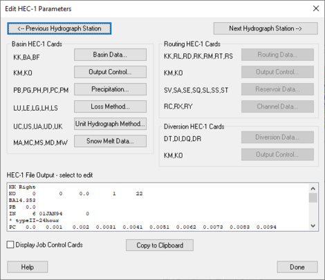
When a basin is selected in the HEC-1 model, selecting HEC-1 | Edit Parameters will bring up the Edit HEC-1 Parameters dialog with the Basin HEC-1 Cards section active. The following can then be specified:
HEC-1 Basin Data Dialog
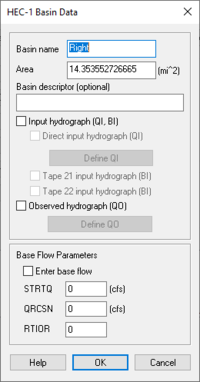
Dialog is accessed by selecting HEC-1 | Edit Parameters... in WMS and then choosing Basin Data... from the Edit HEC-1 Parameters dialog.
Basin name– Each hydrograph station should be identified with a unique name. This name appears as part of the KK record for that station in the input file.
Area – Areas should be entered in either square miles or square kilometers.
Basin Descriptor (Optional) – Option for more Description of the Basin.
Input hydrograph (QI, BI) –
- Direct input hydrograph (QI) – This hydrograph can be input by selecting the checkbox.
- Define QI – Allows for the definition of the direct input hydrograph. Click to open the XY Series Editor dialog.
- Tape 21 input hydrograph (BI) – Select to indicate that the data should be input as a general hydrograph.
- Tape 22 input hydrograph (BI) – Select to indicate that the data should be input as a specific hydrograph.
Observed hydrograph (QO) –
- Define QO – Allows the definition of the outflow hydrograph. Click to open the XY Series Editor dialog.
Base Flow Parameters – Base flow parameters can be defined for a basin by selecting the Enter base flow checkbox. The input parameters for base flow are as follows:
- Enter base flow – Select this to enter the defined base flow.
- STRTQ – Flow at the start of the storm in cfs (cms for metric units).
- QRCSN – Flow in cfs (cms) below which base flow recession occurs in accordance with the recession constant RTIOR. In other words, it is that flow where the straight line (in semilog paper) recession deviates from the falling limb of the hydrograph.
- RTIOR – The ratio of the recession flow (QRCSN) to that flow occurring one hour later (Must be greater than or equal to 1).
HEC-1 Output Control Dialog
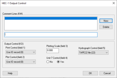
Dialog is accessed by selecting HEC-1 | Edit Parameters... in WMS and then choosing Output Control... from the Edit HEC-1 Parameters dialog.
Comment Lines section – Individual comments can be defined for each hydrograph station. These comments can be used to identify unique characteristics about a particular basin or outlet point.
- New – Select to add a new comment.
- Delete – Select to delete an existing comment.
Output Control (KO) – These controls determine what information about a given hydrograph station is written to the HEC-1 ASCII output file.
- Print Control (field 1) – controls how the data collected is printed.
- "Use IO record (O)" – Default setting, prints the entire IO record.
- "Print all output (1,2)" – When selected, prints all output.
- "Print input and summaries" – When selected, it will just print input and summaries of the data.
- "Print input data only (4)" – When selected, it will print the input data only.
- Plot Control (field 2) – Section where plots can be controlled.
- "Use IO record (O)" – Plots are dependant on the IO record.
- "No printer plots (1)" – Select if there are no printer plots.
- "Plot hydrograph (2)" – Select to receive output on the plot hydrograph.
- Plotting Scale (field 3) – Section to specify the plotting scale.
- Unit 7 Control (field 4) – If the unit 7 control should be on select yes, if not select no.
- Hydrograph Control (field 5) – Section designated to control the output of hydrographs.
- "TAPE22 file (22)" – The file read by WMS for the display of hydrographs. This should only be changed to suppress particular hydrographs.
- "TAPE 21 file (21)" – The file used to suppress particular hydrographs.
For each hydrograph station (basin hydrographs, combined hydrographs, and routed hydrographs) different output controls can be specified. This dialog is accessed by selecting the Output Control dialog button from the Edit HEC-1 Parameters dialog. Entries which can be defined in this dialog are described below.
Routed and Combined Hydrographs at Outlets
In WMS an outlet point is used to represent locations where hydrographs are both combined and then routed. Therefore, if an outlet is selected before choosing the Output Control dialog, a radio group at the top of the dialog appears to specify whether the options should be applied to the combined or routed hydrograph. If a basin is selected the radio group at the top of the dialog does not appear.
HEC-1 Precipitation Dialog
Precipitation patterns are assigned to basins by first selecting the appropriate basin(s) and then clicking on the Precipitation button in the Edit HEC-1 Parameters dialog. If multiple basins are selected then the defined parameters will apply to all selected basins.
- NOTE: If no basins are selected, the parameters can be applied to all basins.
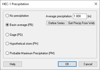
Dialog is accessed by selecting HEC-1|Edit Parameters... in WMS and then choosing Precipitation... from the Edit HEC-1 Parameters dialog.
If no precipitation for a given basin is chosen, then the program will use the precipitation pattern of the most recently defined basin. In other words, if the same precipitation pattern is to be used for each basin, specify precipitation at the upper-most basin and let all other basins "inherit" this same pattern.
No Precipitation – Select if there was no precipitation. Basin average (PB) – Select to specify the Basin Average.
- Average precipitation: – Enter the average precipitation in inches here.
- Define Series – Select to bring up the XY Series Editor dialog.
- Get Precip From Web – Select to bring up the Get Online NOAA Atlas 14 Data dialog.
Gage (PG) – Gages can be used with or without a terrain model. If drainage basins have been defined using a TIN, the appropriate gage weights (using the Thiessen polygon method) for each basin are automatically computed when the Compute (or Update) Basin Data command is executed.
- PT Gage Weights – Section where gage weights can be changed/assigned.
- PR Gage Weights – Section where gage weights can be changed/assigned.
Hypothetical storm (PH) – Select to define the characteristics of a hypothetical storm.
- Define Storm – Select to bring up the XY Series Editor dialog.
- Frequency – Enter the frequency of a hypothetical storm here.
- Storm area: – Enter the area of the hypothetical storm in mi^2.
Probable Maximum Precipitation (PM) – Allows for the computation of the probable maximum storm according to the outdated Hydrometeorological Report No. 33 (HMR 33).
- PMS: – Enter the probable maximum index precipitation from the HMR 33. Recorded in inches.
- % of PMS – Click to bring up the HEC-1 Percentage of PMS dialog.
- Maximum 6-hour percentage of PMS – Maximum amount of probable precipitation inside a 6 hour time period.
- Maximum 12-hour percentage of PMS – Maximum amount of probable precipitation inside a 12 hour time period.
- Maximum 24-hour percentage of PMS – Maximum amount of probable precipitation inside a 24 hour time period.
- Maximum 48-hour percentage of PMS – Maximum amount of probable precipitation inside a 48 hour time period.
- Maximum 72-hour percentage of PMS – Maximum amount of probable precipitation inside a 72 hour time period.
- Maximum 96-hour percentage of PMS – Maximum amount of probable precipitation inside a 96 hour time period.
- SWD – Click to open the Precipitation Distribution dialog.
- EM 1110-2-21411 criteria – Represents the standard flood determinations for the project.
- Southwestern Division criteria – Represents the flood determinations for the southwestern division.
- % of PMS – Click to bring up the HEC-1 Percentage of PMS dialog.
- TRSPC: – Precipitation adjustment (between 0 and 1.0) based on drainage area size. If this value is set at zero HEC-1 will default it to the appropriate value based on the HOP Brook Adjustment Factor as described in the HEC-1 manual.
- TRSDA: – The drainage area in square miles for which the storm is transposed.
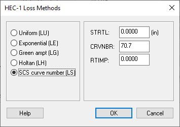
HEC-1 Loss Methods Dialog
Dialog is accessed by selecting HEC-1|Edit Parameters... in WMS and then choosing Loss Method... from the Edit HEC-1 Parameters dialog.
Uniform (LU) – Losses are used in conjunction with the uniform (LU) or exponential (LE) loss methods.
- STRTL – Initial rainfall/snow melt loss in inches (mm) for snow free ground.
- CNSTL – Uniform rainfall/ loss in inches/hour (mm/hour) which is used after the starting loss (STRTL) has been satisfied.
- RTIMP – Ratio of the drainage basin that is impervious. Values should be less than or equal to 1.
Exponential (LE) – Parameters for the exponential loss method are as follows
- STRKR – The starting value of the loss coefficient on the exponential recession curve for rain losses.
- DLTKR – The amount in inches (mm) of initial accumulated rain loss during which the loss coefficient is increased.
- RTIOL – Parameter computed as the ratio of STRKR to a value of STRKR after ten inches (ten mm) of accumulated loss.
- ERAIN – Exponent of precipitation for rain loss function that reflects the influence of the precipitation rate on basin-average loss characteristics.
- RTIMP – Ratio of the drainage basin that is impervious. Values should be less than or equal to 1.
Green ampt (LG) – Green-Ampt infiltration loss parameters are as follows:
- IA – Initial loss (abstraction) in inches (mm).
- DTHETA – Volumetric moisture deficit. If this value is 0, then the method reduces to the initial loss equal to IA and a constant loss equal to XKSAT.
- PSIF – Wetting front suction in inches (mm). If this value is 0, then the method reduces to the initial loss equal to IA and a constant loss equal to XKSAT.
- XKSAT – Hydraulic conductivity at natural saturation in inches/hour (mm/hour).
- RTIMP – Ratio of the drainage basin that is impervious. Values should be less than or equal to 1.
Holtan (LH) – Parameters used to define the Holtan loss method:
- FC – Holtan's long term equilibrium loss rate in inches/hour (mm/hour) for rainfall/losses on snow free ground.
- GIA – Infiltration rate in inches/hour per inch *BEXP (mm/hour per mm *BEXP) of available soil moisture storage capacity.
- SAI – Initial depth in inches (mm) of pore space in the surface layer of the soil which is available for storage of infiltrated water.
- BEXP – Exponent of available soil moisture storage.
- RTIMP – Ratio of the drainage basin that is impervious. Values should be less than or equal to 1.
SCS curve number (LS) – The SCS curve number method uses the following parameters:
- STRTL – Initial rainfall abstraction in inches (mm) for snowfree ground. If value is 0, then initial abstraction will be computed as:
- .
- CRVNBR – SCS curve number for rainfall/ losses on snowfree ground.
NOTE: Composite Curve Numbers can be computed automatically when this method for computing losses is chosen and a terrain model is present.
- RTIMP – Ratio of the drainage basin that is impervious. Values should be less than or equal to 1.
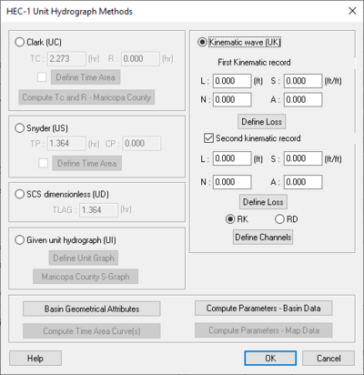
HEC-1 Unit Hydrograph Methods Dialog
One of several different unit hydrograph methods can be chosen when generating synthetic hydrographs. A method is assigned to a basin by first selecting the basin and then choosing the Unit Hydrograph Method button from the Edit HEC-1 Parameters dialog. As with other basin options, the same parameters can be assigned to several basins by selecting multiple basins before accessing the Unit Hydrograph Method dialog.
Dialog is accessed by selecting HEC-1 | Edit Parameters... in WMS and then choosing Unit Hydrograph Method... from the Edit HEC-1 Parameters dialog.
Clark (UC) – Clark Method.
- TC – Time of concentration in hours for the unit hydrograph.
- R: – The Clark storage coefficient in hours.
- Define Time Area – The time area curve defines the area of the watershed contributing runoff to the basin outlet as a function of time. Select to bring up the XY Series Editor dialog.
- Compute Tc and R-Maricopa County – This option is only available when the selection of Green ampt (LG) or Uniform (LU) Loss method in the HEC-1 Loss Methods dialog has been done.
Snyder (US) – Snyder unit hydrograph.
- TP: – Lag time in hours.
- CP: – Peaking coefficient.
- Define Time Area – The time area curve defines the area of the watershed contributing runoff to the basin outlet as a function of time. Select to bring up the XY Series Editor dialog.
SCS dimensionless (UD) – Soil Conservation Services unit hydrograph that contains dimensionless time units and dimensionless discharge units.
- TLAG: – Lag measured in hours.
Given unit hydrograph (UI) – A given unit hydrograph determined from a separate analysis. The given unit hydrograph must be derived for the same time interval as is specified on the IT record in the Job Control dialog.
- Define Unit Graph – Select to bring up the XY Series Editor dialog.
- Maricope County S-Graph – Select this to bring up the S-Graph Option dialog.
- S-Graph Types section – Section that allows the choice of areas within Maricopa County for which an S-Graph will be created.
- "Phoenix Valley" – Area within Maricopa County.
- "Phoenix Mountain" – Area within Maricopa County.
- "Desert rangeland" – Area within Maricopa County.
- "Agricultural" – Represents the agriculture of Maricopa County.
- S-Graph Types section – Section that allows the choice of areas within Maricopa County for which an S-Graph will be created.
- Basin area=31.8901 (sq. miles)
- Basin Lag Time: – Measured in minutes.
- Computational Time Step: – 15 minutes.
Kinematic Wave (UK) – Section of the dialog where you can specify the characteristics attributed to the Kinematic Wave Method.
- First Kinematic Record ‐ Section where the first data found regarding the Kinematic Wave Method can be recorded.
- L: – Represents the Overland flow length (measured in ft).
- S: – Representative slope (measured in ft/ft).
- N: – Represents Manning's roughness coefficient.
- A: – Represents the percentage of sub-basins area that this record represents (The total of the two records must be the sum of 100).
- Define Loss – Click to open the HEC-1 Loss Methods dialog.
- Second Kinematic Record – Section where the second found data regarding the Kinematic Wave Method can be recorded.
- L: – Represents the Overland flow length (measured in ft).
- S: – Representative slope (measured in ft/ft).
- N: – Represents Manning's roughness coefficient.
- A: – Represents the percentage of sub-basins area that this record represents (The total of the two records must be the sum of 100).
- Define Loss – Click to open the HEC-1 Loss Methods dialog.
- RK – Represents the Kinematic Wave routing.
- RD – Represents the Muskingum-Cunge routing.
- Define Channels – Click to open the RK/RD Channels dialog.
- Basin Geometrical Attributes – Select to bring up the Basin Geometric Attributes dialog to define the geometric attributes of the data collected from the Basin.
- Compute Parameters-Basin Data – Select to bring up the Basin Time Computation dialog and compute the parameters of the basin data collected.
- Compute Time Area Curve(s) – Select to bring up the Time Area Parameters dialog that allows you to specify the maximum run off distance and interval to determine the time area curve. (Option is only available when Snyder (US) is selected in the HEC-1 Unit Hydrograph Methods dialog.)
- Compute Parameters-Map Data – Select to determine the parameters of the Map Data.
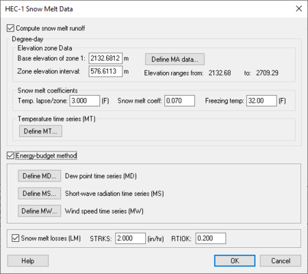
HEC-1 Snow Melt Data Dialog
Dialog is accessed by selecting HEC-1 | Edit Parameters... in WMS and then choosing Snow Melt Data... from the Edit HEC-1 Parameters dialog.
When snow needs to be considered in the runoff analysis, snow melt data for a basin needs to be defined. HEC-1 has two different methods for computing snowfall/melt simulations: the Degree-Day method, and the Energy-Budget.
To define data for a selected basin, choose the Snow Melt Data button from the Edit HEC-1 Parameters dialog. The toggle at the top of the dialog turns snow calculations on. For both methods, the elevation or zone data, the coefficients, and temperature data must be defined.
The Degree-Day method is set up once these parameters have been defined. If the Energy-Budget method is toggled on then the Dew point, Short-wave radiation, and Wind speed data must be defined as well. Losses should be defined when either method is used. These losses are used in conjunction with the LU or LE cards for normal basin losses. The checkbox at the bottom of the dialog allows losses to be turned on or off for a given simulation.
The number of zones that need to be defined is automatically determined and the appropriate edit fields are unhighlighted. The elevation zone parameters are as follows:
- AREA – The drainage area associated with this elevation zone.
- SNOPACK – The snow pack depth.
- AVEPRECIP – The normal annual precipitation in inches (mm) for this zone.
Compute snow melt runoff – Select to allow the input data related to the amount of runoff produced from melting snow.
- Degree-day – Section where elevation data is entered.
- Elevation Zone data – Section where elevation data for each zone is to be entered.
- Base elevation of zone 1: (m) – Elevation data of zone 1.
- Zone elevation interval (m) – Allows the entering of a value for the zone elevation interval.
- Define MA data... – Select to open the Define MA Data dialog which allows you to input variables for the elevation (ft), area (mi^2), snow pack (ft), and Average precipitation (in) for each zone.
- Compute Areas – Select this to open up the Units Dialog and specify model units for computation.
- Snow Melt Coefficients – Section where snow melt coefficients are to be entered.
- Temp. lapse/zone: (F) – Temperature and zone lapse.
- Snow melt Coeff: – Value entered for the amount of snow melt in the area.
- Freezing temp: (F) – Temperature that water freezes.
- Temperature Time Series (MT) – The temperature time series is entered using the XY Series Editor where each value corresponds to the air temperature at the bottom of the lowest elevation zone for that interval. The starting date is determined from the IN record values in the edit fields corresponding to the temperature data.
- Define MT – Select to define the temperature time series and open the XY Series Editor dialog.
- Elevation Zone data – Section where elevation data for each zone is to be entered.
Energy-budget method – Select to allow the input of time series information.
- Define MD... – Represents the Dew point time series (MD). Select to bring up the XY Series Editor dialog.
- Define MS... – Represents the Short-wave radiation time series (MS). Select to bring up the XY Series Editor dialog.
- Define MW... – Represents the Wind-Speed time Series (MW). Select to bring up the XY Series Editor dialog.
Snow melt losses (LM) – Section that allows the input of the amount of loss due to snow melting.
- STRKS – Measured in inches per hour.
- RTIOK – Similar to RTIOL for snow melt.
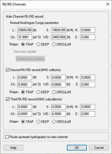
RK/RD Channels Dialog
Accessed by selecting Define Channels in the Kinematic wave section of the HEC-1 Unit Hydrograph Methods dialog. Main Channel RK/RD record
- Normal Muskingum Cunge Parameters
- L – Channel length.
- S – Channel slope.
- N – Manning's roughness.
- Shape – Characteristic channel shape.
- TRAP – Trapezoid.
- DEEP – Deep.
- CIRCULAR – Circular.
- WD – Base width of the channel.
- Z – Side slope of channel.
- Use Cross Section – Select to bring up the Define Cross Section option in this dialog.
- Define Cross Section – Select to bring up the XY Series Editor dialog.
Second RK/RD record (HMS collector) – Select to enter a second RK/RD record.
- L – Channel length.
- S – Channel slope.
- N – Manning's roughness.
- Shape – Characteristic channel shape.
- TRAP – Trapezoid.
- DEEP – Deep.
- CIRCULAR – Circular
- WD – Base width of the channel.
- Z – Side slope of channel.
Third RK/RD record (HMS collector) – Select to enter a third RK/RD record.
- L – Channel length.
- S – Channel slope.
- N – Manning's roughness.
- Shape – Characteristic channel shape.
- TRAP – Trapezoid.
- DEEP – Deep.
- CIRCULAR – Circular.
- WD – Base width of the channel.
- Z – Side slope of channel.
Route upstream hydrographs to main channel – Select to route upstream hydrographs to the main channel.
Related Topics
- HEC-1 Parameters
- Computing Composite CN
- Computing Travel Times
- Computing the Area Between Contours
- XY Series Editor
- Obtaining Precipitation Data
WMS – Watershed Modeling System | ||
|---|---|---|
| Modules: | Terrain Data • Drainage • Map • Hydrologic Modeling • River • GIS • 2D Grid • 2D Scatter |  |
| Models: | CE-QUAL-W2 • GSSHA • HEC-1 • HEC-HMS • HEC-RAS • HSPF • MODRAT • NSS • OC Hydrograph • OC Rational • Rational • River Tools • Storm Drain • SMPDBK • SWMM • TR-20 • TR-55 | |
| Toolbars: | Modules • Macros • Units • Digitize • Static Tools • Dynamic Tools • Drawing • Get Data Tools | |
| Aquaveo | ||
