WMS:Hydrologic Modeling Wizard Overview: Difference between revisions
(→Help) |
|||
| (7 intermediate revisions by 2 users not shown) | |||
| Line 1: | Line 1: | ||
{{TOCright}} | {{TOCright}} | ||
The WMS '''Hydrologic Modeling Wizard''' ([[ | The WMS '''Hydrologic Modeling Wizard''' ([[File:HydrologicModelingWizardIcon.svg|15 px]]) is a simple tool that guides through all the steps involved in creating a hydrologic model. It can be accessed by selecting the '''Hydrologic Modeling Wizard''' tool in the [[WMS:Get Data Toolbar|get data toolbar]] ([[Image:GetDataToolbar1.png]]). | ||
= Steps = | = Steps = | ||
| Line 8: | Line 8: | ||
== Project Filename == | == Project Filename == | ||
[[Image:HydrologicModelingWizardProjectFilename. | [[Image:HydrologicModelingWizardProjectFilename.png|600 px]] | ||
The project filename step is used for defining a project filename. This filename is used when saving files from the hydrologic modeling wizard. | The project filename step is used for defining a project filename. This filename is used when saving files from the hydrologic modeling wizard. | ||
| Line 124: | Line 124: | ||
[[Image:HydrologicModelingWizardDefineAndSmoothStreams.jpg|600 px]] | [[Image:HydrologicModelingWizardDefineAndSmoothStreams.jpg|600 px]] | ||
When building a GSSHA model, | When building a GSSHA model, define the parameters for and smooth all the streams in the model before building the 2D Grid. When the 2D grid is generated, the elevations on cells intersecting stream arcs will be made to match the stream arc channel depth elevations (the stream arc channel depth elevation along the stream = the stream elevation + the channel depth elevation entered in the [[WMS:GSSHA Feature Arcs|GSSHA Feature Arc Type dialog]]). | ||
=== Help === | === Help === | ||
'''Select one or more streams''' – This button selects the '''Select Feature Arc''' tool. After this tool is selected, | '''Select one or more streams''' – This button selects the '''Select Feature Arc''' tool. After this tool is selected, select one or more stream arcs and edit the attributes or smooth the selected stream arcs. | ||
'''Select a stream branch''' – This button selects the [[WMS:Map Tools|'''Select Stream Branch''' tool]]. This is a specialized tool that selects a stream arc and any arcs upstream from the selected arc. This tool is useful for selecting an entire stream network or a branch of a stream network. | '''Select a stream branch''' – This button selects the [[WMS:Map Tools|'''Select Stream Branch''' tool]]. This is a specialized tool that selects a stream arc and any arcs upstream from the selected arc. This tool is useful for selecting an entire stream network or a branch of a stream network. | ||
'''Set Selected Arc Attributes''' – This button brings up the [[WMS:GSSHA Feature Arcs|''GSSHA Feature Arc Type'' dialog]]. This dialog allows | '''Set Selected Arc Attributes''' – This button brings up the [[WMS:GSSHA Feature Arcs|''GSSHA Feature Arc Type'' dialog]]. This dialog allows setting the attributes for all the selected arcs. | ||
'''Redistribute Vertices on All Streams''' – Selecting this button will first switch the active coverage to be the GSSHA coverage. If no arcs are selected, all the stream arcs will be selected in the GSSHA coverage. If arcs are selected, no additional arcs will be selected. The [[WMS:Feature Objects Menu#Redistribute|''Redistribute Vertices'']] dialog will appear | '''Redistribute Vertices on All Streams''' – Selecting this button will first switch the active coverage to be the GSSHA coverage. If no arcs are selected, all the stream arcs will be selected in the GSSHA coverage. If arcs are selected, no additional arcs will be selected. The [[WMS:Feature Objects Menu#Redistribute|''Redistribute Vertices'']] dialog will appear which allows setting a new spacing for the vertices on the selected arcs. | ||
'''Smooth Selected Stream Segments''' – This button will bring up the [[WMS:GSSHA | '''Smooth Selected Stream Segments''' – This button will bring up the [[WMS:Smooth GSSHA Streams|''Smooth GSSHA Streams'']] dialog for the selected arc(s). Before selecting this button, select a set of non-branched stream arcs. The smooth streams dialog has several options for modifying and smoothing the streams in the selected branch. | ||
== Create 2D Grid == | == Create 2D Grid == | ||
| Line 166: | Line 166: | ||
=== Help === | === Help === | ||
'''Create Coverages''' – | '''Create Coverages''' – Defines the land use and soil type shapefiles. A model coverage and the land use/soil data will be transferred to coverages in the map module then clipped to the watershed boundary. | ||
== Hydrologic Computations == | == Hydrologic Computations == | ||
| Line 176: | Line 176: | ||
=== Help === | === Help === | ||
'''Compute GIS Attributes''' – Depending on the model being used, this button brings up a dialog | '''Compute GIS Attributes''' – Depending on the model being used, this button brings up a dialog which can compute attributes from the land use and/or soil type data. | ||
'''Travel times''' – This spreadsheet allows | '''Travel times''' – This spreadsheet allows computing the Time of Concentration for all the sub-basins in the watershed using either the basin data or map data method. | ||
'''Edit Parameters''' – This button brings up the | '''Edit Parameters''' – This button brings up the ''Edit Parameters'' dialog for the model to change modeling parameters for all the sub-basins in the watershed. | ||
== Define Precipitation == | == Define Precipitation == | ||
| Line 190: | Line 190: | ||
=== Help === | === Help === | ||
'''Compute Precipitation''' (certain models only) – This button allows | '''Compute Precipitation''' (certain models only) – This button allows computing the precipitation for the model from a NOAA Atlas 2 or any other type of rainfall grid. | ||
'''Define Precipitation''' – This button allows | '''Define Precipitation''' – This button allows defining precipitation for the selected model. | ||
== Clean Up Model == | == Clean Up Model == | ||
[[Image:HydrologicModelingWizardCleanUpModel. | [[Image:HydrologicModelingWizardCleanUpModel.png|600 px|600 px]] | ||
The Clean Up Model step is used to clean up the model by doing tasks that are typically done when the model is finished. | The Clean Up Model step is used to clean up the model by doing tasks that are typically done when the model is finished. | ||
Latest revision as of 18:07, 15 January 2024
The WMS Hydrologic Modeling Wizard (![]() ) is a simple tool that guides through all the steps involved in creating a hydrologic model. It can be accessed by selecting the Hydrologic Modeling Wizard tool in the get data toolbar (
) is a simple tool that guides through all the steps involved in creating a hydrologic model. It can be accessed by selecting the Hydrologic Modeling Wizard tool in the get data toolbar (![]() ).
).
Steps
The following steps are included in the hydrologic modeling wizard:
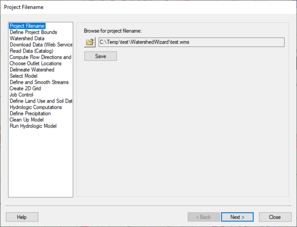
Project Filename
The project filename step is used for defining a project filename. This filename is used when saving files from the hydrologic modeling wizard.
Help
Save – This button saves the project in the current state.
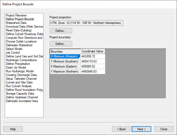
Define Project Bounds
The define project bounds step is used for defining the project boundary.
Help
Top Define button – This button is used to define the project coordinate system, if it is known.
Bottom Define button – This button is used to define the project boundary in the Microsoft Virtual Earth web service client. Find the area to be modeled and WMS will enter the minimum and maximum coordinates of the box defined in the Virtual Earth window.
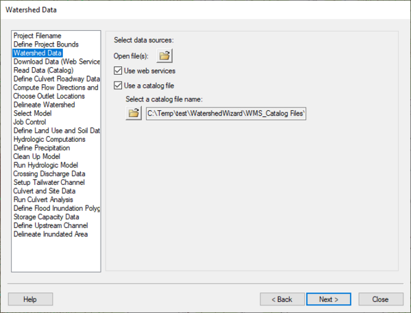
Watershed Data
The watershed data step is used for defining how the project will read data into WMS. Obtain data using the WMS web service client, a catalog file, or by simply opening files.
Help
Open file button – Use this button in the same way as the File | Open command in the WMS menus. After selecting this button, a file browser appears and WMS opens the files selected.
Web services – WMS will use the built-in web service client for obtaining data for watershed modeling.
Catalog file – WMS will use a catalog file for obtaining data for watershed modeling.
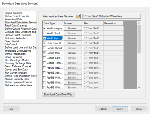
Download Data
The download data (web service client) step is used to download data over the internet using the WMS web service client if a web service is available. NED and SRTM data may be downloaded from this dialog, but coverage may not exist or download times may be slow for the hydrologic modeling area. The NED and SRTM data are obtained from USGS databases. The Terraserver data are obtained from the Microsoft Research (MSR) Maps web service.
Help
Download Data From Web – This button downloads the selected datasets for the selected modeling area from the web service providers.
Read Data
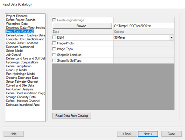
The read data from catalog step is used to select and read data from a WMS catalog.
Help
Read Data From Catalog – This button reads data from the catalog inside the selected project boundary.
Compute Flow Directions and Flow Accumulations
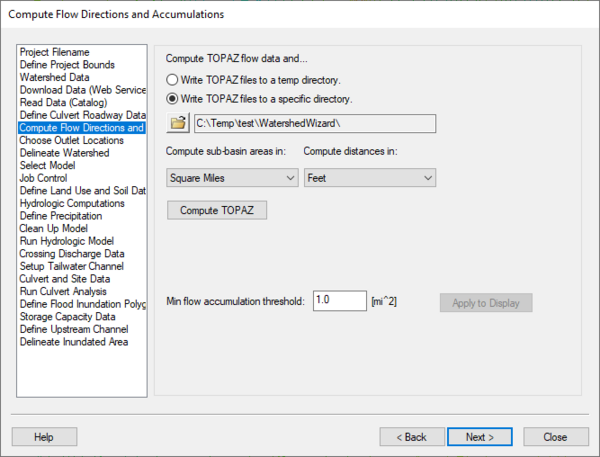
The Compute Flow Directions and Flow Accumulations step is used for running TOPAZ to compute flow directions and accumulations.
Help
Compute TOPAZ flow data and... – Choose either to write the TOPAZ output to a specific directory or to the temp directory. Most frequently, write the TOPAZ output to a temp directory.
Units – Use the units combo boxes to define the model's computation units.
Compute Topaz – This button runs TOPAZ using the selected settings.
Choose Outlet Locations
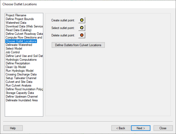
The Choose Outlet Locations step is used to define, move, or delete outlet locations.
Help
Create, Select, and Delete outlet point buttons – To create an outlet point, select a tool to use and then click on a flow accumulation cell. To select an outlet point, select the tool and click on a point or drag a point. To delete a point, select a tool and select an outlet point to delete.
In the HY-8 Modeling Wizard, this dialog has a Define Outlets from Culvert Locations button. This button defines an outlet at the point on a flow accumulation cell that is closest to the upstream end of the culvert arc.
Delineate Watershed
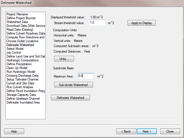
The Delineate Watershed step is used to delineate a watershed.
Help
Stream threshold value – This value is used to modify the stream density. Lower values will cause the streams to be more dense while higher values will create fewer streams in the completed model.
Apply to Display – Select this button to apply the stream threshold value entered to the display.
Create Tc Coverage – If this toggle is selected, a Time Computation coverage containing an arc with the longest flow path is created after delineating the watershed and sub-basins.
Units – This button is used to define the model and computation coordinates and units. Turn on the option to create a Tc coverage and change which data is computed by selecting the Drain Data Compute Opts... button in the Units dialog.
Sub-divide Watershed – This button subdivides the watershed into sub-basins based on the maximum sub-basin area entered.
Delineate Watershed – This button delineates the watershed and computes each sub-basin's data based on the selected watershed delineation parameters.
After delineating a watershed, it is possible to manually edit the extents of the watershed.
Select Model
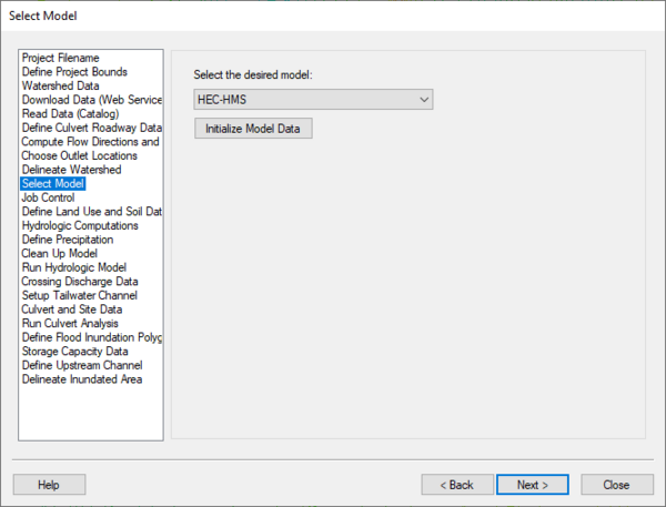
The Select Model step is used for defining which model to run with the delineated watershed.
Help
Initialize Model Data – Click on this button to set the model to the selected option, initialize ther model data to default values, and set the module to the correct module.
Define and Smooth Streams
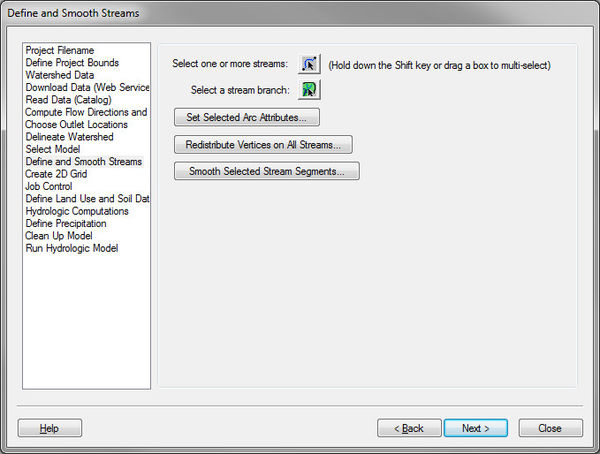
When building a GSSHA model, define the parameters for and smooth all the streams in the model before building the 2D Grid. When the 2D grid is generated, the elevations on cells intersecting stream arcs will be made to match the stream arc channel depth elevations (the stream arc channel depth elevation along the stream = the stream elevation + the channel depth elevation entered in the GSSHA Feature Arc Type dialog).
Help
Select one or more streams – This button selects the Select Feature Arc tool. After this tool is selected, select one or more stream arcs and edit the attributes or smooth the selected stream arcs.
Select a stream branch – This button selects the Select Stream Branch tool. This is a specialized tool that selects a stream arc and any arcs upstream from the selected arc. This tool is useful for selecting an entire stream network or a branch of a stream network.
Set Selected Arc Attributes – This button brings up the GSSHA Feature Arc Type dialog. This dialog allows setting the attributes for all the selected arcs.
Redistribute Vertices on All Streams – Selecting this button will first switch the active coverage to be the GSSHA coverage. If no arcs are selected, all the stream arcs will be selected in the GSSHA coverage. If arcs are selected, no additional arcs will be selected. The Redistribute Vertices dialog will appear which allows setting a new spacing for the vertices on the selected arcs.
Smooth Selected Stream Segments – This button will bring up the Smooth GSSHA Streams dialog for the selected arc(s). Before selecting this button, select a set of non-branched stream arcs. The smooth streams dialog has several options for modifying and smoothing the streams in the selected branch.
Create 2D Grid
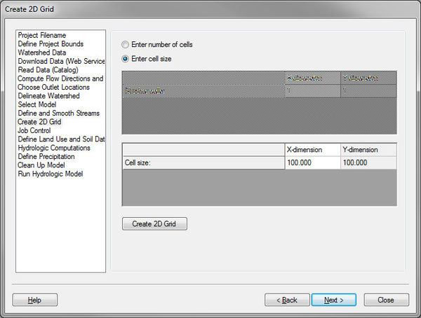
The Create 2D Grid step is used to create a 2D grid from the watershed boundary. Select a grid cell size or number of cells and select the Create 2D Grid button to create a 2D grid.
Help
Create 2D Grid – This button creates a 2D grid based on the cell size or number of cells entered. For the GSSHA or ModClark models to run correctly, the X and Y dimensions of the 2D grid cells must be equal.
HMW Job Control
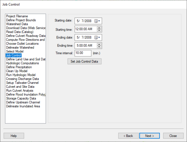
The job control step is used define the time parameters for running the model. Define the start and end time and date and select Set Job Control Data to set the job control parameters for the selected model.
Help
Set Job Control Data – Sets the job control parameters for the selected model.
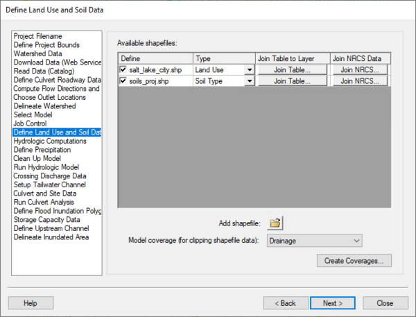
Define Land Use and Soil Data
The Define Land Use and Soil Data step converts GIS Module shapefiles to data in the WMS Map module. WMS uses the boundary of the watershed to clip the shapefile data for the selected files.
Help
Create Coverages – Defines the land use and soil type shapefiles. A model coverage and the land use/soil data will be transferred to coverages in the map module then clipped to the watershed boundary.
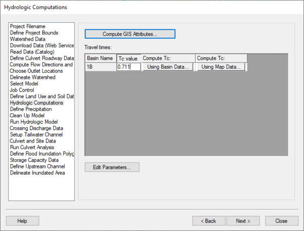
Hydrologic Computations
The Hydrologic Computations step is used to compute hydrologic parameters for the watershed and sub-basins.
Help
Compute GIS Attributes – Depending on the model being used, this button brings up a dialog which can compute attributes from the land use and/or soil type data.
Travel times – This spreadsheet allows computing the Time of Concentration for all the sub-basins in the watershed using either the basin data or map data method.
Edit Parameters – This button brings up the Edit Parameters dialog for the model to change modeling parameters for all the sub-basins in the watershed.
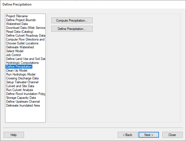
Define Precipitation
The Define Precipitation step is used to compute and define precipitation for the model.
Help
Compute Precipitation (certain models only) – This button allows computing the precipitation for the model from a NOAA Atlas 2 or any other type of rainfall grid.
Define Precipitation – This button allows defining precipitation for the selected model.
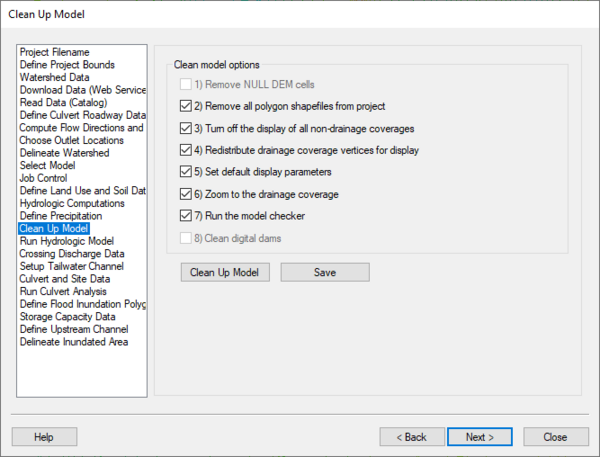
Clean Up Model
The Clean Up Model step is used to clean up the model by doing tasks that are typically done when the model is finished.
Help
Clean Up Model – This button runs only the selected tasks listed above the button.
Save – This button saves the project in the current state.
WMS – Watershed Modeling System | ||
|---|---|---|
| Modules: | Terrain Data • Drainage • Map • Hydrologic Modeling • River • GIS • 2D Grid • 2D Scatter |  |
| Models: | CE-QUAL-W2 • GSSHA • HEC-1 • HEC-HMS • HEC-RAS • HSPF • MODRAT • NSS • OC Hydrograph • OC Rational • Rational • River Tools • Storm Drain • SMPDBK • SWMM • TR-20 • TR-55 | |
| Toolbars: | Modules • Macros • Units • Digitize • Static Tools • Dynamic Tools • Drawing • Get Data Tools | |
| Aquaveo | ||
