GMS:Feature Objects: Difference between revisions
From XMS Wiki
Jump to navigationJump to search
| (3 intermediate revisions by one other user not shown) | |||
| Line 1: | Line 1: | ||
{{Map links}} | {{Map links}} | ||
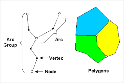
Feature objects in GMS have been patterned after Geographic Information Systems (GIS) objects and include points, nodes, arcs, and polygons. Feature objects can be grouped together into coverages, each coverage defining a particular set of information. Since feature objects are patterned after GIS objects, it is possible to [[GMS:Importing/Exporting Shapefiles|import and export]] feature objects to a GIS such as Arc/Info or ArcView. | Feature objects in GMS have been patterned after Geographic Information Systems (GIS) objects and include points, nodes, arcs, and polygons. Feature objects can be grouped together into coverages, each coverage defining a particular set of information. Since feature objects are patterned after GIS objects, it is possible to [[GMS:Importing/Exporting Shapefiles|import and export]] feature objects to a GIS program such as Arc/Info or ArcView. | ||
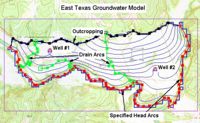
The primary use of feature objects is to generate a high level conceptual model representation of a site. In such a model, items such as rivers, drains, wells, lakes are represented with points, arcs, and polygons. Attributes such as conductance, pumping rates, and elevations are defined with the objects. This conceptual model is then used to automatically generate a grid or mesh and assign the boundary conditions and model parameters to the appropriate cells. Thus, the user can focus on a simplified, high level representation of the model and little or no tedious cell-by-cell editing is required. The feature object approach can be used to build models for [[GMS:SEEP2D|SEEP2D]], [[GMS:FEMWATER|FEMWATER]], [[GMS:MODFLOW|MODFLOW]], [[GMS:MT3DMS|MT3DMS]], [[GMS:RT3D|RT3D]], and [[GMS:SEAM3D|SEAM3D]]. Feature objects are also used to construct cross sections. | The primary use of feature objects is to generate a high level conceptual model representation of a site. In such a model, items such as rivers, drains, wells, lakes are represented with points, arcs, and polygons. Attributes such as conductance, pumping rates, and elevations are defined with the objects. This conceptual model is then used to automatically generate a grid or mesh and assign the boundary conditions and model parameters to the appropriate cells. Thus, the user can focus on a simplified, high level representation of the model and little or no tedious cell-by-cell editing is required. The feature object approach can be used to build models for [[GMS:SEEP2D|SEEP2D]], [[GMS:FEMWATER|FEMWATER]], [[GMS:MODFLOW|MODFLOW]], [[GMS:MT3DMS|MT3DMS]], [[GMS:RT3D|RT3D]], and [[GMS:SEAM3D|SEAM3D]]. Feature objects are also used to construct cross sections. | ||
| Line 53: | Line 53: | ||
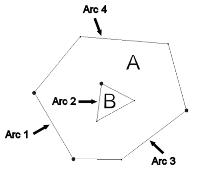
:[[Image:polygons.png|thumb|none|400 px|Polygon with holes]] | :[[Image:polygons.png|thumb|none|400 px|Polygon with holes]] | ||
;'''Build Polygons''' : While most feature objects can be constructed with [[GMS:Feature Object Tool Palette|tools]] in the Tool Palette, polygons are constructed with the '''Build Polygons''' command. Since polygons are defined by arcs, the first step in constructing a polygon is to create the arcs forming the boundary of the polygon. Once the arcs are created, they should be selected with the [[GMS:Feature Object Tool Palette|Select Arc]] tool, and the '''Build Polygons''' command should be selected from the ''Feature Objects'' menu. If the selected arcs do not form a valid loop, an error message is given. | |||
:While most feature objects can be constructed with [[GMS:Feature Object Tool Palette|tools]] in the Tool Palette, polygons are constructed with the '''Build Polygons''' command. Since polygons are defined by arcs, the first step in constructing a polygon is to create the arcs forming the boundary of the polygon. Once the arcs are created, they should be selected with the [[GMS:Feature Object Tool Palette|Select Arc]] tool, and the '''Build Polygons''' command should be selected from the ''Feature Objects'' menu. If the selected arcs do not form a valid loop, an error message is given. | |||
:The '''Build Polygons''' command can be used to construct one polygon at a time or to construct several polygons at once. If the selected arcs form a single loop, only one polygon is created. If the arcs form multiple loops, a polygon is created for each unique (non-overlapping) loop. If no arcs are selected, all of the currently defined arcs in the active coverage are used to create polygons. | :The '''Build Polygons''' command can be used to construct one polygon at a time or to construct several polygons at once. If the selected arcs form a single loop, only one polygon is created. If the arcs form multiple loops, a polygon is created for each unique (non-overlapping) loop. If no arcs are selected, all of the currently defined arcs in the active coverage are used to create polygons. | ||
| Line 64: | Line 63: | ||
In a generic sense, a conceptual model is a simplified, high level model of a site. In GMS, a conceptual model object consists of a set of coverages which are tied to a particular numerical model like MODFLOW or FEMWATER. The coverages below a conceptual model can have attributes that are related to the numerical model. For example, a coverage below a MODFLOW conceptual model can have drain or river arcs. | In a generic sense, a conceptual model is a simplified, high level model of a site. In GMS, a conceptual model object consists of a set of coverages which are tied to a particular numerical model like MODFLOW or FEMWATER. The coverages below a conceptual model can have attributes that are related to the numerical model. For example, a coverage below a MODFLOW conceptual model can have drain or river arcs. | ||
== | ==Attribute Table== | ||
The '' | The ''Attribute Table'' dialog is used to edit the properties of points, nodes, arcs, arc groups, and polygons. Three filters are located at the top of the dialog. | ||
The ''Feature type'' | The ''Feature type'' drop-down is used to choose which feature (point, arcs...) the spreadsheet displays. The ''Show'' drop-down will show only the selected features or all features depending on which option is selected. The ''BC type'' drop-down is used to display only certain boundary conditions. For example, if the filter is changed to "well," then only the wells would be displayed in the spreadsheet. | ||
The ''Show | The ''Show coordinates'' checkbox is used to display the (x, y, z) coordinates of each point in the spreadsheet. The '''Add Point''' and '''Delete Point''' buttons are used to create new points or remove points from the coverage. | ||
The spreadsheet displays an attribute table associated with the current feature type (point, arc...). The columns available in the spreadsheet depend on the options selected in [[GMS:Coverages|''Coverage Setup'']] dialog. | The spreadsheet displays an attribute table associated with the current feature type (point, arc...). The columns available in the spreadsheet depend on the options selected in the [[GMS:Coverages|''Coverage Setup'']] dialog. | ||
[[Category:GMS Dialogs|F]] | [[Category:GMS Dialogs|F]] | ||
