WMS:TR-20 Routing Data: Difference between revisions
No edit summary |
|||
| (2 intermediate revisions by one other user not shown) | |||
| Line 1: | Line 1: | ||
[[File:TR20routingdata. | [[File:TR20routingdata.png|thumb|400 px|Example of the ''TR-20 Routing Data'' dialog.]] | ||
Outlet points are used to define locations where hydrographs are combined and then routed downstream. The appropriate combined hydrograph (ADDHYD records) stations are generated automatically when writing a TR-20 file. However, routing data must be entered in order to simulate the movement of a flood wave through the river reaches or reservoirs. The effects of storage and flow resistance are accounted for in the shape and timing of the flood wave. | Outlet points are used to define locations where hydrographs are combined and then routed downstream. The appropriate combined hydrograph (ADDHYD records) stations are generated automatically when writing a TR-20 file. However, routing data must be entered in order to simulate the movement of a flood wave through the river reaches or reservoirs. The effects of storage and flow resistance are accounted for in the shape and timing of the flood wave. | ||
| Line 7: | Line 7: | ||
''Define Reach Routing'' – Select to define the reach routing data for the project. | ''Define Reach Routing'' – Select to define the reach routing data for the project. | ||
Kinematic Wave'' – The kinematic wave method uses two different rating coefficients, x and m, in the following equation: | ''Kinematic Wave'' – The kinematic wave method uses two different rating coefficients, x and m, in the following equation: | ||
:<math>Q = xA^m </math> | :<math>Q = xA^m </math> | ||
where ''Q'' is the discharge, ''A'' is the valley storage area divided by length and ''x'' and ''m'' are the coefficient and exponent of the relationship describing the reach and maximum inflow hydrograph peak discharge. | where ''Q'' is the discharge, ''A'' is the valley storage area divided by length and ''x'' and ''m'' are the coefficient and exponent of the relationship describing the reach and maximum inflow hydrograph peak discharge. | ||
''Direct Input Hydrographs'' – | |||
Hydrographs can be input directly, and then routed down stream, using the different routing options. To do this, select the ''Direct Input Hydrograph'' option. Hit the '''New''' button in the ''Define input hydrographs'' dialog to define a new hydrograph. The base flow and contributing drainage area for the hydrograph should be entered for computation purposes. | |||
'''Define Input Hydrograph''' – One or more input hydrographs can be defined for a reservoir. WMS will combine any input hydrographs with other input hydrographs to the reservoir. The resulting hydrograph will then be routed through the reservoir. This option is useful for defining the measured stream flows into a reservoir. | |||
==Routing Method== | ==Routing Method== | ||
| Line 35: | Line 40: | ||
==Outlet Names== | ==Outlet Names== | ||
Since outlets are used for both types (adding and routing) of hydrograph stations in the TR-20 input file, a separate name for each type of hydrograph must be entered. The name should be eight characters or less and is used to read hydrographs from the results file. | Since outlets are used for both types (adding and routing) of hydrograph stations in the TR-20 input file, a separate name for each type of hydrograph must be entered. The name should be eight characters or less and is used to read hydrographs from the results file. | ||
The hydrograph may be edited by selecting the '''Edit''' button after selecting the hydrograph to edit. For each input hydrograph in TR-20, the discharge in cfs at each time interval must be entered. | The hydrograph may be edited by selecting the '''Edit''' button after selecting the hydrograph to edit. For each input hydrograph in TR-20, the discharge in cfs at each time interval must be entered. | ||
Latest revision as of 21:00, 13 December 2023
Outlet points are used to define locations where hydrographs are combined and then routed downstream. The appropriate combined hydrograph (ADDHYD records) stations are generated automatically when writing a TR-20 file. However, routing data must be entered in order to simulate the movement of a flood wave through the river reaches or reservoirs. The effects of storage and flow resistance are accounted for in the shape and timing of the flood wave.
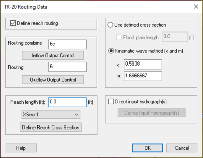
TR-20 Routing Data Dialog
Routing data is entered by selecting an outlet and then selecting the Routing Data button from the Edit TR-20 Parameters dialog.
Define Reach Routing – Select to define the reach routing data for the project.
Kinematic Wave – The kinematic wave method uses two different rating coefficients, x and m, in the following equation:
where Q is the discharge, A is the valley storage area divided by length and x and m are the coefficient and exponent of the relationship describing the reach and maximum inflow hydrograph peak discharge.
Direct Input Hydrographs – Hydrographs can be input directly, and then routed down stream, using the different routing options. To do this, select the Direct Input Hydrograph option. Hit the New button in the Define input hydrographs dialog to define a new hydrograph. The base flow and contributing drainage area for the hydrograph should be entered for computation purposes.
Define Input Hydrograph – One or more input hydrographs can be defined for a reservoir. WMS will combine any input hydrographs with other input hydrographs to the reservoir. The resulting hydrograph will then be routed through the reservoir. This option is useful for defining the measured stream flows into a reservoir.
Routing Method
TR-20 has two different routing methods to choose from. If cross-sectional data is available it can be used to establish routing parameters using a “m-value” method. If the cross section data are not available a Kinematic wave method may be used instead. The method for each outlet is determined by the radio group selection.
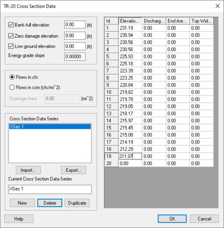
TR-20 Cross Section Data Dialog
With this routing method a typical cross section for each reach (outlet) must be defined. This is done using the TR-20 Cross Section Data dialog, and is accessed by selecting the Define Cross Section Data button.
Bankfull Elevation – When entering the bankfull elevation here, it will trigger a warning message in the TR-20 output file if less than two cross section data points are below bankfull. Entering the bankfull elevation is optional.
Zero Damage Elevation – This is used with the TR-20 flow duration analysis to flag results at this elevation. Entering the zero damage elevation is optional.
Low Ground Elevation – The low ground elevation is the lowest floodplain elevation in a cross-section. The low ground elevation, which is optional, must not be higher than the bankfull elevation.
Flow Units – The flow can be entered in cubic feet per second per square mile (csm) or cubic feet per second (cfs). To select one of these flows, simply select the type of flow by selecting the appropriate radio button in the Define Cross Section dialog. If flow is defined in csm, define the drainage area of the basin in square miles.
Defining Cross Sections – Once a cross section has been defined in TR-20, this cross section can be used in other locations in the TR-20 model. A cross section defined for an earlier outlet can be used later by another outlet simply by selecting the name from the text window or the drop-down box in the TR-20 Routing Data dialog.
Reach Length
This value should be the length, in feet, along the river reach for which routing takes place. If a TIN, DEM, or map-based watershed model is present this value is automatically computed and assigned to this field whenever the Compute Basin Data command is executed. A cross section must be assigned to the reach length assigned.
Outlet Names
Since outlets are used for both types (adding and routing) of hydrograph stations in the TR-20 input file, a separate name for each type of hydrograph must be entered. The name should be eight characters or less and is used to read hydrographs from the results file.
The hydrograph may be edited by selecting the Edit button after selecting the hydrograph to edit. For each input hydrograph in TR-20, the discharge in cfs at each time interval must be entered.
Related Topics
WMS – Watershed Modeling System | ||
|---|---|---|
| Modules: | Terrain Data • Drainage • Map • Hydrologic Modeling • River • GIS • 2D Grid • 2D Scatter |  |
| Models: | CE-QUAL-W2 • GSSHA • HEC-1 • HEC-HMS • HEC-RAS • HSPF • MODRAT • NSS • OC Hydrograph • OC Rational • Rational • River Tools • Storm Drain • SMPDBK • SWMM • TR-20 • TR-55 | |
| Toolbars: | Modules • Macros • Units • Digitize • Static Tools • Dynamic Tools • Drawing • Get Data Tools | |
| Aquaveo | ||


