WMS:Diversion HEC-1 Cards: Difference between revisions
| (2 intermediate revisions by 2 users not shown) | |||
| Line 1: | Line 1: | ||
[[Image:Edit HEC-1 Parameters. | [[Image:Edit HEC-1 Parameters.png|thumb|470 px|''Edit HEC-1 Parameters'' dialog]] | ||
==''HEC-1 Diversion Data'' Dialog== | ==''HEC-1 Diversion Data'' Dialog== | ||
HEC-1 allows flow to be diverted from an outlet or drainage basin. This flow can be thought of as leaving the normal drainage system at that point. It can be retrieved at a downstream outlet where the diverted flow then contributes to the flow at that outlet. If no downstream retrieval outlet point is specified, the flow simply leaves the system at the diverted outlet point and never returns. | HEC-1 allows flow to be diverted from an outlet or drainage basin. This flow can be thought of as leaving the normal drainage system at that point. It can be retrieved at a downstream outlet where the diverted flow then contributes to the flow at that outlet. If no downstream retrieval outlet point is specified, the flow simply leaves the system at the diverted outlet point and never returns. | ||
Diversions are created using a combination of the '''Add | Diversion''' and '''Retrieve Diversion''' commands found in the ''Tree'' menu. Once created, data for the diversion can be defined and/or edited by selecting the '''Diversion Data''' button from the ''Edit HEC-1 Parameters'' dialog. | Diversions are created using a combination of the '''Add | Diversion''' and '''Retrieve Diversion''' commands found in the ''Tree'' menu. Once created, data for the diversion can be defined and/or edited by selecting the '''Diversion Data''' button from the ''Edit HEC-1 Parameters'' dialog. | ||
[[Image: HEC-1_Diversion_Data.PNG|Thumb|300 px|''HEC-1 Diversion Data'' dialog]] | [[Image: HEC-1_Diversion_Data.PNG|Thumb|300 px|''HEC-1 Diversion Data'' dialog]] | ||
| Line 25: | Line 26: | ||
==''HEC-1 Output Control'' Dialog== | ==''HEC-1 Output Control'' Dialog== | ||
[[Image:HEC1 Output Control. | [[Image:HEC1 Output Control.png|thumb|400 px|''HEC-1 Output Control'' dialog]] | ||
Dialog is accessed by selecting ''HEC-1'' | '''Edit Parameters...''' in WMS and then choosing '''Output Control...''' from the ''Edit HEC-1 Parameters'' dialog. | Dialog is accessed by selecting ''HEC-1'' | '''Edit Parameters...''' in WMS and then choosing '''Output Control...''' from the ''Edit HEC-1 Parameters'' dialog. | ||
Latest revision as of 22:44, 13 July 2020
HEC-1 Diversion Data Dialog
HEC-1 allows flow to be diverted from an outlet or drainage basin. This flow can be thought of as leaving the normal drainage system at that point. It can be retrieved at a downstream outlet where the diverted flow then contributes to the flow at that outlet. If no downstream retrieval outlet point is specified, the flow simply leaves the system at the diverted outlet point and never returns.
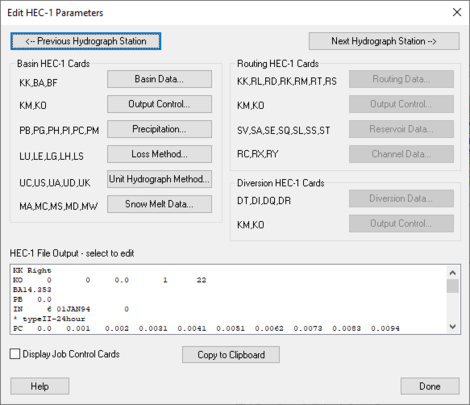
Diversions are created using a combination of the Add | Diversion and Retrieve Diversion commands found in the Tree menu. Once created, data for the diversion can be defined and/or edited by selecting the Diversion Data button from the Edit HEC-1 Parameters dialog.
Accessed by right-clicking on a basin in the graphics window, selecting Add | Diversion and selecting New Diversion... in the Defined Diversions dialog.
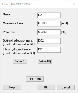
Name: – The name identification string of the diversion as used on the DT record. It is important to assign a unique name to each diversion in a given model because this name is used by WMS and by HEC-1 to identify the diversion.
Maximum Volume: – Maximum volume of diverted flow in acre-feet (1000 cu m).
Peak Flow: – Peak flow that can be diverted in any computation period in cfs (cms).
Outflow Hydrograph Name: (Used on KK record for DT) – Name used on KK record where flow is diverted.
Inflow Hydrograph Name: (Used on KK record for DR) – Name used on KK record where flow is retrieved.
Define DI – Select to bring up the XY Series Editor dialog and define inflow.
Define DQ – Select to bring up the XY Series Editor dialog and define outflow.
Plot DI-DQ – Select to bring up the HEC Plot dialog and see a visual representation of the inflow and outflow points.
HEC-1 Output Control Dialog
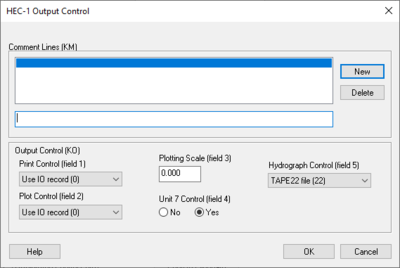
Dialog is accessed by selecting HEC-1 | Edit Parameters... in WMS and then choosing Output Control... from the Edit HEC-1 Parameters dialog.
Comment Lines section – Individual comments can be defined for each hydrograph station. These comments can be used to identify unique characteristics about a particular basin or outlet point.
- New – Select to add a new comment.
- Delete – Select to delete an existing comment.
Output Control (KO) – These controls determine what information about a given hydrograph station is written to the HEC-1 ASCII output file.
- Print Control (field 1) – controls how the data collected is printed.
- "Use IO record (O)" – Default setting, prints the entire IO record.
- "Print all output (1,2)" – When selected, prints all output.
- "Print input and summaries" – When selected, it will just print input and summaries of the data.
- "Print input data only (4)" – When selected, it will print the input data only.
- Plot Control (field 2) – Section where plots can be controlled.
- "Use IO record (O)" – Plots are dependant on the IO record.
- "No printer plots (1)" – Select if there are no printer plots.
- "Plot hydrograph (2)" – Select to receive output on the plot hydrograph.
- Plotting Scale (field 3) – Section to specify the plotting scale.
- Unit 7 Control (field 4) – If the unit 7 control should be on select yes, if not select no.
- Hydrograph Control (field 5) – Section designated to control the output of hydrographs.
- "TAPE22 file (22)" – The file read by WMS for the display of hydrographs. This should only be changed to suppress particular hydrographs.
- "TAPE 21 file (21)" – The file used to suppress particular hydrographs.
For each hydrograph station (basin hydrographs, combined hydrographs, and routed hydrographs) different output controls can be specified. This dialog is accessed by selecting the Output Control dialog button from the Edit HEC-1 Parameters dialog. Entries which can be defined in this dialog are described below.
Routed and Combined Hydrographs at Outlets
In WMS an outlet point is used to represent locations where hydrographs are both combined and then routed. Therefore, if an outlet is selected before choosing the Output Control dialog, a radio group at the top of the dialog appears to specify whether the options should be applied to the combined or routed hydrograph. If a basin is selected the radio group at the top of the dialog does not appear.
Related Topics
WMS – Watershed Modeling System | ||
|---|---|---|
| Modules: | Terrain Data • Drainage • Map • Hydrologic Modeling • River • GIS • 2D Grid • 2D Scatter |  |
| Models: | CE-QUAL-W2 • GSSHA • HEC-1 • HEC-HMS • HEC-RAS • HSPF • MODRAT • NSS • OC Hydrograph • OC Rational • Rational • River Tools • Storm Drain • SMPDBK • SWMM • TR-20 • TR-55 | |
| Toolbars: | Modules • Macros • Units • Digitize • Static Tools • Dynamic Tools • Drawing • Get Data Tools | |
| Aquaveo | ||


