WMS:HEC-1 Job Control: Difference between revisions
No edit summary |
|||
| (67 intermediate revisions by 3 users not shown) | |||
| Line 1: | Line 1: | ||
[[Image:HEC1JobControlDialog.png|thumb| | [[Image:HEC1JobControlDialog.png|thumb|350 px|''HEC-1 Job Control'' dialog]] | ||
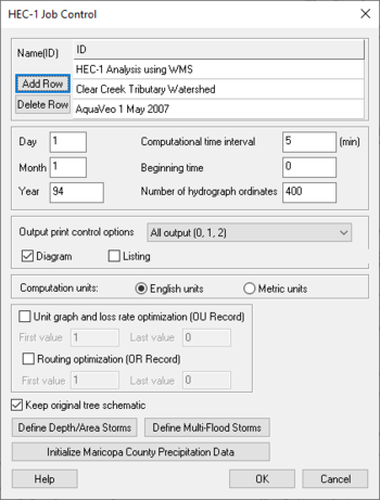
The ''Job Control'' dialog is used to define general information about the HEC-1 model. Selecting the '''Job Control''' command from the ''HEC-1'' menu accesses this dialog. The ''Job Control'' dialog can also be accessed by toggling on the display of Job Control cards in the [[WMS:HEC-1 Parameters|''Edit HEC-1 Parameters'']] dialog and then clicking on a ''Job Control'' related card in the text display window. | |||
*''Name (ID)'' | |||
*:Enter a name and/or project description identifying the model. Three different name records up to 78 characters each can be entered. The name records will appear at the top of the HEC-1 input file. | |||
*''Add Row'' – Addition of rows to be applied. | |||
*''Delete Row'' – Exclusion of Rows to be applied. | |||
*''Beginning Time'' – The beginning time of the simulation is defined in this entry. The time should be specified as a single integer number defining the hours and minutes. For example, 7:45 am would be entered as 745 and 1:15 PM would be 1315. Do not place a colon between the hours and minutes. | |||
*''Computation Time Interval (min)'' – The computational time interval defines the length in time between hydrograph ordinates. The interval should be specified in minutes, with 1 being the minimum. The total simulation time of the model will be the number of ordinates minus one multiplied by the computational time interval. | |||
*''Day Month Year (IT)''– The day, month, and year fields correspond to the date of the first computational time interval. The year is entered as the last two digits only. | |||
*::'''''NOTE:''''' The date should be consistent with dates defined on IN records for precipitation and other time series data. | |||
*''Number of hydrograph ordinates'' – The number of hydrograph ordinates computed during the simulation is defined in this entry. The length of the simulation is determined by the number of ordinates times the computational interval. If a simulation is run and a complete hydrograph is not developed, then the number of ordinates can be increased to increase the length of the simulation. Similarly, the number of ordinates can be decreased if the simulation continues long past the falling limb of the hydrograph. | |||
*''Output Control Options (IO)'' – In the ''HEC-1 Job Control'' dialog, there is an option to set ''Output print control options''. HEC-1 generates an ASCII output file that can be printed or read into any standard word processing program. The information output is controlled by the ''Output print control options'' in the ''HEC-1 Job Control'' dialog. | |||
*''Listing (*LISTING)'' – Causes HEC-1 to echo print input data. | |||
*''Tree Diagram (*DIAGRAM)'' – The diagram option causes a diagram of the stream network to be printed to the HEC-1 output file. This diagram should appear similar to the tree representation created by WMS. | |||
*''Units (IM)'' – By default HEC-1 performs computations in English units, however metric unit calculations can be specified. | |||
*''Basin Data Optimization (OU)'' – Select this option if wanting to optimize unit hydrograph and loss rate parameters in this HEC-1 simulation so the calculated hydrograph will match the observed hydrograph. | |||
*''Routing Optimization (OR)'' – Select this option if wanting to optimize routing parameters using observed inflow and outflow hydrographs and a pattern lateral inflow hydrograph for the routing reach. | |||
*''Keep original tree schematic'' – Turn this option off to sort the hydrologic tree from the tree branches with the most nodes to the branches with the fewest nodes when writing the HEC-1 input file. Note that the original tree schematic ordering will not be preserved when this option is turned off. This option is useful when saving HEC-1 files containing diversions that have been retrieved from large watersheds to smaller watersheds. See [[WMS:Topologic_Trees#Retrieving_Diversions|retrieving diversions]] for more information. | |||
* ''Depth Area Storms (JD)'' – See [[WMS:HEC-1 Job Control#Depth Area Storms|Depth Area Storms below]]. | |||
*'' MultiFlood Storms (JR)'' – See [[WMS:HEC-1 Job Control#MultiFlood Storms|MultiFlood Storms below]]. | |||
== | ==Depth Area Storms== | ||
[[Image:HEC1depthareastorm.png|thumb|300 px|HEC-1 ''Depth/Area Storm'' dialog]] | |||
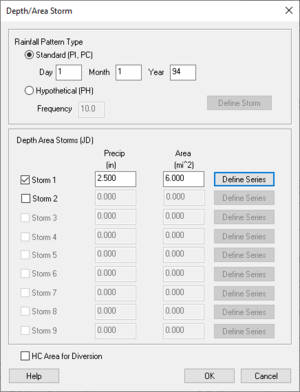
Runoff simulations that use a consistent depth/area relationship as defined in the HEC-1 User's Manual[http://www.hec.usace.army.mil/software/legacysoftware/hec1/hec1-documentation.htm] can be defined by clicking on the '''Define Depth/Area Storms''' button to bring up the dialog shown below. | |||
*''Rainfall Pattern Type'' – Each storm (JD record) may be defined with a set of PI/PC cards giving the precipitation pattern to be used for that depth and area. If no pattern is given for the second through ninth storms then the previously defined precipitation pattern will be used. | |||
::Alternatively hypothetical storms may be used to specify precipitation patterns. In such cases, only a single storm using the PH record needs to be defined. | |||
::The rainfall pattern type is specified using the radio group at the top of the dialog. As a new storm is activated, data fields that require input will be undimmed. Data fields that do not apply to the specified pattern type will remain dimmed. | |||
*''Depth Area Storms'' – Different depth/area storms can be defined by toggling on a storm from within the ''Depth/Area Storms'' portion of the dialog. | |||
*''Precipitation'' – The average precipitation is entered in this data field. | |||
*''Area'' – The applicable area for this storm is entered in this data field. | |||
*'''Defining a Series''' | |||
*:If a standard storm type has been chosen, a rainfall pattern must be defined using the XY Series Editor. Activate the [[WMS:XY Series Editor|''XY Series Editor'']] by choosing the '''Define Series''' button. A series for the first storm must be defined. If a series is not defined for the second through ninth storms, the previously defined storm will be used. | |||
The rainfall pattern type is specified using the radio group at the top of dialog. As a new storm is activated, data fields | |||
Different depth/area storms can be defined by toggling on a storm from within the Depth/Area Storms portion of the dialog. | |||
The average precipitation is entered in this data field. | |||
The applicable area for this storm is entered in this data field. | |||
If a standard storm type has been chosen, a rainfall pattern must be defined using the XY Series Editor. Activate the [[WMS:XY Series Editor|XY Series Editor]] by choosing the Define Series button. A series for the first storm must be defined. If a series is not defined for the second through ninth storms, the previously defined storm will be used. | |||
==MultiFlood Storms== | |||
[[Image:HEC1multifloodstorms.png|thumb|200 px|HEC-1 ''Multiple Storms'' dialog]] | |||
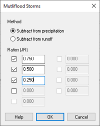
Multiple ratios of a given storm event can be specified by bringing up the Multi-flood dialog using the '''Define Multi-Flood Storms''' button. The data input options are described below. | Multiple ratios of a given storm event can be specified by bringing up the Multi-flood dialog using the '''Define Multi-Flood Storms''' button. The data input options are described below. | ||
*''Method'' – Input ratios can be specified using either precipitation or runoff. | |||
*''Ratios'' – Up to nine different storm ratios can be specified by toggling on the appropriate checkbox. All hydrograph or precipitation ordinates are multiplied by the specified value. | |||
Input ratios can be specified using either precipitation or runoff. | |||
Up to nine different storm ratios can be specified by toggling on the appropriate | |||
Each storm is analyzed during execution of HEC-1 and the resulting TAPE22 file will contain as many hydrographs for each station as there are ratios defined. Display of different storm ratios can be toggled on and off in the ''Hydrologic Modeling'' tab of the ''Display Options'' dialog. | ::Each storm is analyzed during the execution of HEC-1 and the resulting TAPE22 file will contain as many hydrographs for each station as there are ratios defined. Display of different storm ratios can be toggled on and off in the ''Hydrologic Modeling'' tab of the ''Display Options'' dialog. | ||
==Related Topics== | ==Related Topics== | ||
| Line 100: | Line 50: | ||
{{WMSMain}} | {{WMSMain}} | ||
[[Category:HEC-1|J]] | |||
[[Category:HEC-1 Dialogs]] | |||
[[Category:OC Unit Dialogs]] | |||
[[Category:External Links]] | |||
[[Category:WMS Job Control|HEC-1]] | |||
Latest revision as of 17:07, 23 May 2022
The Job Control dialog is used to define general information about the HEC-1 model. Selecting the Job Control command from the HEC-1 menu accesses this dialog. The Job Control dialog can also be accessed by toggling on the display of Job Control cards in the Edit HEC-1 Parameters dialog and then clicking on a Job Control related card in the text display window.
- Name (ID)
- Enter a name and/or project description identifying the model. Three different name records up to 78 characters each can be entered. The name records will appear at the top of the HEC-1 input file.
- Add Row – Addition of rows to be applied.
- Delete Row – Exclusion of Rows to be applied.
- Beginning Time – The beginning time of the simulation is defined in this entry. The time should be specified as a single integer number defining the hours and minutes. For example, 7:45 am would be entered as 745 and 1:15 PM would be 1315. Do not place a colon between the hours and minutes.
- Computation Time Interval (min) – The computational time interval defines the length in time between hydrograph ordinates. The interval should be specified in minutes, with 1 being the minimum. The total simulation time of the model will be the number of ordinates minus one multiplied by the computational time interval.
- Day Month Year (IT)– The day, month, and year fields correspond to the date of the first computational time interval. The year is entered as the last two digits only.
- NOTE: The date should be consistent with dates defined on IN records for precipitation and other time series data.
- Number of hydrograph ordinates – The number of hydrograph ordinates computed during the simulation is defined in this entry. The length of the simulation is determined by the number of ordinates times the computational interval. If a simulation is run and a complete hydrograph is not developed, then the number of ordinates can be increased to increase the length of the simulation. Similarly, the number of ordinates can be decreased if the simulation continues long past the falling limb of the hydrograph.
- Output Control Options (IO) – In the HEC-1 Job Control dialog, there is an option to set Output print control options. HEC-1 generates an ASCII output file that can be printed or read into any standard word processing program. The information output is controlled by the Output print control options in the HEC-1 Job Control dialog.
- Listing (*LISTING) – Causes HEC-1 to echo print input data.
- Tree Diagram (*DIAGRAM) – The diagram option causes a diagram of the stream network to be printed to the HEC-1 output file. This diagram should appear similar to the tree representation created by WMS.
- Units (IM) – By default HEC-1 performs computations in English units, however metric unit calculations can be specified.
- Basin Data Optimization (OU) – Select this option if wanting to optimize unit hydrograph and loss rate parameters in this HEC-1 simulation so the calculated hydrograph will match the observed hydrograph.
- Routing Optimization (OR) – Select this option if wanting to optimize routing parameters using observed inflow and outflow hydrographs and a pattern lateral inflow hydrograph for the routing reach.
- Keep original tree schematic – Turn this option off to sort the hydrologic tree from the tree branches with the most nodes to the branches with the fewest nodes when writing the HEC-1 input file. Note that the original tree schematic ordering will not be preserved when this option is turned off. This option is useful when saving HEC-1 files containing diversions that have been retrieved from large watersheds to smaller watersheds. See retrieving diversions for more information.
- Depth Area Storms (JD) – See Depth Area Storms below.
- MultiFlood Storms (JR) – See MultiFlood Storms below.
Depth Area Storms
Runoff simulations that use a consistent depth/area relationship as defined in the HEC-1 User's Manual[1] can be defined by clicking on the Define Depth/Area Storms button to bring up the dialog shown below.
- Rainfall Pattern Type – Each storm (JD record) may be defined with a set of PI/PC cards giving the precipitation pattern to be used for that depth and area. If no pattern is given for the second through ninth storms then the previously defined precipitation pattern will be used.
- Alternatively hypothetical storms may be used to specify precipitation patterns. In such cases, only a single storm using the PH record needs to be defined.
- The rainfall pattern type is specified using the radio group at the top of the dialog. As a new storm is activated, data fields that require input will be undimmed. Data fields that do not apply to the specified pattern type will remain dimmed.
- Depth Area Storms – Different depth/area storms can be defined by toggling on a storm from within the Depth/Area Storms portion of the dialog.
- Precipitation – The average precipitation is entered in this data field.
- Area – The applicable area for this storm is entered in this data field.
- Defining a Series
- If a standard storm type has been chosen, a rainfall pattern must be defined using the XY Series Editor. Activate the XY Series Editor by choosing the Define Series button. A series for the first storm must be defined. If a series is not defined for the second through ninth storms, the previously defined storm will be used.
MultiFlood Storms
Multiple ratios of a given storm event can be specified by bringing up the Multi-flood dialog using the Define Multi-Flood Storms button. The data input options are described below.
- Method – Input ratios can be specified using either precipitation or runoff.
- Ratios – Up to nine different storm ratios can be specified by toggling on the appropriate checkbox. All hydrograph or precipitation ordinates are multiplied by the specified value.
- Each storm is analyzed during the execution of HEC-1 and the resulting TAPE22 file will contain as many hydrographs for each station as there are ratios defined. Display of different storm ratios can be toggled on and off in the Hydrologic Modeling tab of the Display Options dialog.
Related Topics
WMS – Watershed Modeling System | ||
|---|---|---|
| Modules: | Terrain Data • Drainage • Map • Hydrologic Modeling • River • GIS • 2D Grid • 2D Scatter |  |
| Models: | CE-QUAL-W2 • GSSHA • HEC-1 • HEC-HMS • HEC-RAS • HSPF • MODRAT • NSS • OC Hydrograph • OC Rational • Rational • River Tools • Storm Drain • SMPDBK • SWMM • TR-20 • TR-55 | |
| Toolbars: | Modules • Macros • Units • Digitize • Static Tools • Dynamic Tools • Drawing • Get Data Tools | |
| Aquaveo | ||


