User:Rcorrigan/Sandboxing GMS Menus: Difference between revisions
No edit summary |
No edit summary |
||
| Line 39: | Line 39: | ||
[[Category:GMS Menus]] | [[Category:GMS Menus]] | ||
[[Category:GMS General Information]] | [[Category:GMS General Information]] | ||
==Units== | |||
[[File:GMSunits.png|thumb|250 px|The ''Units'' dialog.]] | |||
When building a ground water model, it is important to ensure that consistent units are used when entering model parameters. To simplify the management of model units, define the units for length, time, mass, force and concentration in the ''Units'' dialog. A units label is placed next to each of the input fields in all the model dialogs in GMS where the units are known. For example, the units for hydraulic conductivity are length / time. If the length units are defined as "m" (meters) and the time units are defined as "d" (days) in the ''Units'' dialog, then the units string next to the hydraulic conductivity input field would be "m/d". | |||
''Length'' units are specified in the [[Projections|''Display Projection'']] dialog which is accessed by clicking on the [[File:Dot dot dot button.png|28px]] button to the right. | |||
Concentration units can be defined separately, and potentially inconsistently with, mass and length units. This allows for more flexibility but can also lead to confusion so use care when selecting concentration units. | |||
The ''Units'' dialog is accessed by using the '''Units...''' command in the ''Edit'' menu. | |||
==Unit Conversion== | |||
Generally speaking, GMS does not convert quantities from one system of units to another. GMS only displays the chosen units to help in checking consistancy. However, in a few places, GMS will use the currently defined units in it's calculations. These include: | |||
* in the [[GMS:FEMWATER_Model_Input#Fluid_Properties|''FEMWATER Fluid Properties'']] dialog, | |||
* in the [[GMS:FEMWATER_Model_Input#Curve_Generator|''Curve Generator'']] dialog, | |||
* when calculating the stream stage constant when saving MODFLOW, and | |||
* in the [[GMS:Toolbars#Static_Tool_Palette|'''Measure''']] tool. | |||
==See also== | |||
*[[GMS:Edit Menu|Edit Menu]] | |||
{{Navbox GMS}} | |||
[[Category:GMS General Information]] | |||
[[Category:GMS Dialogs|U]] | |||
[[Category:Preferences]] | |||
Revision as of 17:18, 14 March 2022
The Edit menu is one of the standard menus and is available in all of the modules. The commands in the Edit menu are used to select objects, delete objects, and set basic object and material attributes. The Edit menu contains the following commands:
- Delete
- Deletes the object currently selected in the Graphics Window.
- Select All
- Selects all items associated with the current selection tool.
- Unselect All
- Unselects all items associated with the current selection tool.
- Invert Selection
- Selects the items that were not initially selected and are associated with the current selection tool.
- Select With Poly
- Used to enter a polygon enclosing the items to be selected (one of the selection tools must be active). This option is useful when selecting a large irregularly shaped group of objects. To enter the polygon, click on the polygon's starting point and each intermediate point defining the polygon and double-click on the ending point. All items within the polygon will be selected.
- Select With Polyline
- Selects the items that intersect a polyline associated with the current selection tool.
- Select From List
- Brings up a list of objects associated with the current selection tool. An object is selected by checking the box next to it in the list and clicking OK. This tool only works with boreholes,cross sections, and solids.
- Select by ID
- Brings up a selection dialog where cells or objects in the selected module can be selected by the ID number.
- Select By Dataset Value
- Opens the Select By Dataset Value dialog that allows selecting nodes or cells based on the dataset values when the current tool corresponds to one which selects nodes or cells and there is a dataset associated with the nodes or cells. Select either the less than or greater than options, or both.
- Locate Selections
- Causes a rectangle to be drawn on screen and move to surround the location of the selected items, helping to see where they are.
- Selection Window
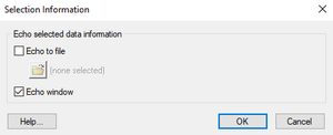
- Brings up the Selection Information dialog allowing to turn on and off the echo of the information to a file and to a separate, dockable window. When objects are selected, various information about the objects can be displayed or saved. The values are displayed by default in the Status Bar at the bottom of the GMS main window. However, since space along the bottom of the window is limited, there is the option of displaying the information to a separate window and optionally echoing the information into a file. ??
- Dataset Calculator
- Brings up the Data Calculator which can be used to perform mathematical operations with datasets to create new datasets.
- Properties
- Brings up the Properties dialog for the currently selected item.
- Materials
- Brings up the Material Properties dialog.
- Notes
- Brings up the Notes dialog showing all notes for all objects in the project.
- Model Interfaces
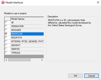
- Brings up the Model Interfaces dialog containing a list of all available models. Selecting models in this dialog determines which model menus are to be displayed in the menu bar.
- Units
- Brings up the Units dialog which allows adjusting the units for the model.
- Time
- Opens the Time Settings dialog which allows adjusting how date and time units are displayed.
- Single Point Reprojection...
- Brings up the Reproject Single Point dialog that allows transforming a point between coordinate systems.
- Transform...
- Brings up the Transform dialog allowing to scale, rotate and translate the entire project. Individual objects can be transformed by using the same command found in right-click context menus for the item in the Project Explorer.
- Preferences
- Brings up the Preferences dialog where it is possible to adjust the general preferences for GMS.
- Screen Capture...
- Copies the Graphics Window as an image to the Windows clipboard. If wanting to copy an image that is larger or smaller than the graphics window, edit the Bitmap scale factor in the Preferences dialog. Brings up the Copy To Clipboard dialog which allows changing the Bitmap scale factor. However, the clipboard has a limited amount of memory available to it; thus, GMS may not be able to scale the image up as much as it could when saving the file to disk. If a screen capture will not paste into another program, try reducing the scale factor.
- Paste Text
- Allows pasting tabular data directly into GMS. When this command is executed the File Import Wizard is launched.
Obsolete Menu Items
The following commands have been removed from current versions of GMS:
- Coordinate System
- Brings up the Coordinate System dialog which allows adjusting the current horizontal and vertical coordinate systems.
- Coordinate Transformation
- Brings up the Coordinate Transformation Wizard which allows performing geographic system transformations, translations, rotations, and scaling.
Related Topics
GMS – Groundwater Modeling System | ||
|---|---|---|
| Modules: | 2D Grid • 2D Mesh • 2D Scatter Point • 3D Grid • 3D Mesh • 3D Scatter Point • Boreholes • GIS • Map • Solid • TINs • UGrids | |
| Models: | FEFLOW • FEMWATER • HydroGeoSphere • MODAEM • MODFLOW • MODPATH • mod-PATH3DU • MT3DMS • MT3D-USGS • PEST • PHT3D • RT3D • SEAM3D • SEAWAT • SEEP2D • T-PROGS • ZONEBUDGET | |
| Aquaveo | ||
Units
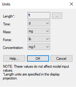
When building a ground water model, it is important to ensure that consistent units are used when entering model parameters. To simplify the management of model units, define the units for length, time, mass, force and concentration in the Units dialog. A units label is placed next to each of the input fields in all the model dialogs in GMS where the units are known. For example, the units for hydraulic conductivity are length / time. If the length units are defined as "m" (meters) and the time units are defined as "d" (days) in the Units dialog, then the units string next to the hydraulic conductivity input field would be "m/d".
Length units are specified in the Display Projection dialog which is accessed by clicking on the ![]() button to the right.
button to the right.
Concentration units can be defined separately, and potentially inconsistently with, mass and length units. This allows for more flexibility but can also lead to confusion so use care when selecting concentration units.
The Units dialog is accessed by using the Units... command in the Edit menu.
Unit Conversion
Generally speaking, GMS does not convert quantities from one system of units to another. GMS only displays the chosen units to help in checking consistancy. However, in a few places, GMS will use the currently defined units in it's calculations. These include:
- in the FEMWATER Fluid Properties dialog,
- in the Curve Generator dialog,
- when calculating the stream stage constant when saving MODFLOW, and
- in the Measure tool.
See also
GMS – Groundwater Modeling System | ||
|---|---|---|
| Modules: | 2D Grid • 2D Mesh • 2D Scatter Point • 3D Grid • 3D Mesh • 3D Scatter Point • Boreholes • GIS • Map • Solid • TINs • UGrids | |
| Models: | FEFLOW • FEMWATER • HydroGeoSphere • MODAEM • MODFLOW • MODPATH • mod-PATH3DU • MT3DMS • MT3D-USGS • PEST • PHT3D • RT3D • SEAM3D • SEAWAT • SEEP2D • T-PROGS • ZONEBUDGET | |
| Aquaveo | ||


