WMS:OC Rational Reach Routing: Difference between revisions
No edit summary |
|||
| Line 1: | Line 1: | ||
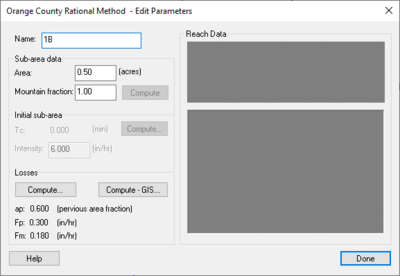
[[Image:WMSmain.jpg|thumb|400 px|''Orange County Rational Method – Edit Parameters'' dialog]] | [[Image:WMSmain.jpg|thumb|400 px|''Orange County Rational Method – Edit Parameters'' dialog]] | ||
Reach routing data is assigned to the upstream node of each reach. Select a node and use the '''Edit Parameters''' command in the ''OC Rational'' menu to define data. | Reach routing data is assigned to the upstream node of each reach. Select a node and use the '''Edit Parameters''' command in the ''OC Rational'' menu to define data. The user can select another node at any time while the ''Orange County Rational Method – Edit Parameters'' dialog is displayed and view its reach data. | ||
===Entering Parameters=== | ===Entering Parameters=== | ||
Revision as of 16:32, 11 September 2014
Reach routing data is assigned to the upstream node of each reach. Select a node and use the Edit Parameters command in the OC Rational menu to define data. The user can select another node at any time while the Orange County Rational Method – Edit Parameters dialog is displayed and view its reach data.
Entering Parameters
Toggle on the checkboxes next to each routing type and select the conveyance type to use any combination of surface (streets and trapezoidal channels) and sub-surface (pipes and culverts) routing. Enter parameters for the highlighted routing type in the spreadsheet below. Values for reach length, up elevation, down elevation, and slope will be computed if using GIS data.
Routing Computations
Flow will be routed through subsurface conveyance types first and then any excess flow will be routed using the surface conveyance type, if defined. Overflow messages will be displayed in the output report.
Design/Analysis Mode
There is a design and analysis mode if using sub-surface circular pipes. Enter the actual pipe diameter for the analysis mode or enter 0.0 for the pipe diameter to use the design mode. The design mode will calculate the smallest standard pipe to carry the computed flow. View the design pipe size here after running a simulation.
Related Topics
WMS – Watershed Modeling System | ||
|---|---|---|
| Modules: | Terrain Data • Drainage • Map • Hydrologic Modeling • River • GIS • 2D Grid • 2D Scatter |  |
| Models: | CE-QUAL-W2 • GSSHA • HEC-1 • HEC-HMS • HEC-RAS • HSPF • MODRAT • NSS • OC Hydrograph • OC Rational • Rational • River Tools • Storm Drain • SMPDBK • SWMM • TR-20 • TR-55 | |
| Toolbars: | Modules • Macros • Units • Digitize • Static Tools • Dynamic Tools • Drawing • Get Data Tools | |
| Aquaveo | ||
