GMS:Feature Objects
Feature objects in GMS have been patterned after Geographic Information Systems (GIS) objects and include points, nodes, arcs, and polygons. Feature objects can be grouped together into coverages, each coverage defining a particular set of information. Since feature objects are patterned after GIS objects, it is possible to import and export feature objects to a GIS program such as Arc/Info or ArcView.
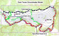
The primary use of feature objects is to generate a high level conceptual model representation of a site. In such a model, items such as rivers, drains, wells, lakes are represented with points, arcs, and polygons. Attributes such as conductance, pumping rates, and elevations are defined with the objects. This conceptual model is then used to automatically generate a grid or mesh and assign the boundary conditions and model parameters to the appropriate cells. Thus, the user can focus on a simplified, high level representation of the model and little or no tedious cell-by-cell editing is required. The feature object approach can be used to build models for SEEP2D, FEMWATER, MODFLOW, MT3DMS, RT3D, and SEAM3D. Feature objects are also used to construct cross sections.
Contents
Object Types
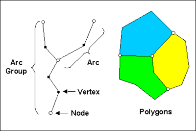
The definition of feature objects in GMS follows the paradigm used by typical GIS software that supports vector data. The basic object types are points, nodes, vertices, arcs, arc groups, and polygons. The relationship between these objects is illustrated in the following figure.
Points
Points are XY locations that are not attached to an arc. Points have unique IDs and can be assigned attributes. Points are often used to represent wells. Points are also used when importing a set of XY locations for the purpose of creating arcs or polygons.
Arcs
Arcs are sequences of line segments or edges which are grouped together as a single "polyline" entity. Arcs have unique IDs and can be assigned attributes. Arcs are grouped together to form polygons or are used independently to represent linear features such as rivers. The two end points of an arc are called "nodes" and the intermediate points are called "vertices".
- Create Arc Group
- This command is used to create an arc group from a set of selected arcs. Once the arc group is created, it can be selected using the Select Arc Group tool. Properties can be assigned to the arc group as a whole, and the arc group can be selected to display the computed flow through the arc group. An arc group is deleted by selecting the arc group and selecting the Delete key. Deleting an arc group does not delete the underlying arcs.
- Reverse Arc Direction
- Each arc has a direction. One node is the "from" node, the other node is the "to" node. For most applications, the direction of the arc does not matter. However, when the arc is used to define a MODFLOW stream network, the direction of the arc becomes significant. The Reverse Arc Direction command can be used to change the direction (upstream to downstream) for a stream type arc.
Nodes
Nodes define the beginning and ending XY locations of an arc. Nodes have unique IDs and can be assigned attributes.
Vertices
Vertices are XY locations along arcs in between the beginning and ending nodes. They are used solely to define the geometry of the arcs. Vertices do not have IDs or attributes.
- Redistribute Vertices
- The primary function of the vertices of an arc is to define the geometry of the arc. In most cases, the spacing of the vertices does not matter. However, if the arcs are to be used for automatic mesh generation, the spacing of the vertices is important. In this case, the spacing of the vertices defines the density of the elements in the resulting mesh. Each edge defined by a pair of vertices becomes the edge of an element. The mesh gradation is controlled by defining closely spaced vertices in regions where the mesh is to be dense and widely spaced vertices in regions where the mesh is to be coarse.
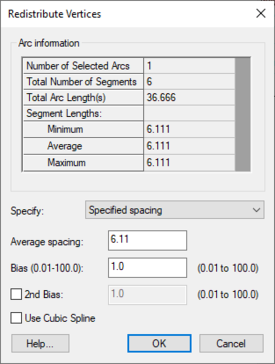
- When spacing vertices along arcs, the Redistribute vertices command in the Feature Objects menu can be used to automatically create a new set of vertices along a selected set of arcs at either a higher or lower density. The desired arc should be selected prior to selecting the Redistribute vertices command. The Redistribute vertices command brings up the Redistribute Vertices dialog. The following options are available for redistributing vertices:
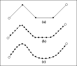
- Linear Interpolation – If the Linear interpolation option is specified, then either a number of subdivisions or a target spacing can be given to determine how points are redistributed along the selected arcs. In either case, the new vertices are positioned along a linear interpolation of the original arc.
- Spline Interpolation – If the Spline interpolation option is specified, vertices are redistributed along a series of cubic splines defined by the original vertices of the selected arcs. The difference between the linear and spline interpolation methods is illustrated below:
- Vertex to Node
- In some cases, it is necessary to split an arc into two arcs. This can be accomplished using the Vertex ↔ Node command. Before selecting this command, a vertex on the arc at the location where the arc is to be split should be selected. The selected vertex is converted to a node and the arc is split in two.
- The Vertex ↔ Node command can also be used to combine two adjacent arcs into a single arc. This is accomplished by converting the node joining the two arcs into a vertex. Two arcs can only be merged if no other arcs are connected to the node separating the arcs. Otherwise, the node must be preserved to define the junction between the branching arcs.
Arc Groups
An arc group is a set of arcs that has been marked as a group by the user. As an arc group, attributes can be assigned to the entire group rather than to individual arcs. An arc group can also be selected as a single unit. Arc groups are primarily used for flow observations.
Polygons
Polygons are a group of connected arcs that form a closed loop. A polygon can consist of a single arc or multiple arcs. If two polygons are adjacent, the arc(s) forming the boundary between the polygons is shared (not duplicated).
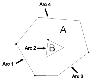
Polygons may not overlap. However, a polygon can have a hole defined by having a set of closed arcs defining interior polygons. An example of such a case is shown in the figure below where three arcs are used to define two polygons. Polygon A is made up of arcs 1, 2, 3 and 4, whereas polygon B is defined by a single arc (arc 2). For polygon A arcs 1, 3, and 4 define the exterior boundary whereas arc 2 defines a hole.
Polygons have unique IDs and can be assigned attributes. Polygons are used to represent material zones, lakes, variable head zones, etc.
- Build Polygons
- While most feature objects can be constructed with tools in the Tool Palette, polygons are constructed with the Build Polygons command. Since polygons are defined by arcs, the first step in constructing a polygon is to create the arcs forming the boundary of the polygon. Once the arcs are created, they should be selected with the Select Arc tool, and the Build Polygons command should be selected from the Feature Objects menu. If the selected arcs do not form a valid loop, an error message is given.
- The Build Polygons command can be used to construct one polygon at a time or to construct several polygons at once. If the selected arcs form a single loop, only one polygon is created. If the arcs form multiple loops, a polygon is created for each unique (non-overlapping) loop. If no arcs are selected, all of the currently defined arcs in the active coverage are used to create polygons.
Coverages
Feature objects are grouped together into coverages. Each coverage represents a particular set of data. For example, one coverage can be used to define recharge zones, and another coverage can be used to define zones of hydraulic conductivity.
Conceptual Models
In a generic sense, a conceptual model is a simplified, high level model of a site. In GMS, a conceptual model object consists of a set of coverages which are tied to a particular numerical model like MODFLOW or FEMWATER. The coverages below a conceptual model can have attributes that are related to the numerical model. For example, a coverage below a MODFLOW conceptual model can have drain or river arcs.
Attribute Table
The Attribute Table dialog is used to edit the properties of points, nodes, arcs, arc groups, and polygons. Three filters are located at the top of the dialog.
The Feature type drop-down is used to choose which feature (point, arcs...) the spreadsheet displays. The Show drop-down will show only the selected features or all features depending on which option is selected. The BC type drop-down is used to display only certain boundary conditions. For example, if the filter is changed to "well," then only the wells would be displayed in the spreadsheet.
The Show coordinates checkbox is used to display the (x, y, z) coordinates of each point in the spreadsheet. The Add Point and Delete Point buttons are used to create new points or remove points from the coverage.
The spreadsheet displays an attribute table associated with the current feature type (point, arc...). The columns available in the spreadsheet depend on the options selected in the Coverage Setup dialog.
Converting Feature Objects
Feature objects can be converted to other data types in GMS such as cross sections and scatter points. This can be accomplished by either right-clicking on a conceptual model, coverage, grid frame, or by selecting a command from the Feature Objects menu. These commands are summarized on the following pages.
| [hide]GMS – Groundwater Modeling System | ||
|---|---|---|
| Modules: | 2D Grid • 2D Mesh • 2D Scatter Point • 3D Grid • 3D Mesh • 3D Scatter Point • Boreholes • GIS • Map • Solid • TINs • UGrids | |
| Models: | FEFLOW • FEMWATER • HydroGeoSphere • MODAEM • MODFLOW • MODPATH • mod-PATH3DU • MT3DMS • MT3D-USGS • PEST • PHT3D • RT3D • SEAM3D • SEAWAT • SEEP2D • T-PROGS • ZONEBUDGET | |
| Aquaveo | ||
