WMS:Routing HEC-1 Cards
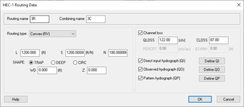
HEC-1 Routing Data Dialog
Outlet points are used to define locations where hydrographs are combined and then routed downstream. The appropriate combined hydrograph (HC cards) stations are generated automatically when writing a HEC-1 file. However, routing data must be entered in order to simulate the movement of a flood wave through the river reaches or reservoirs. The effects of storage and flow resistance are accounted for in the shape and timing of the flood wave. In addition to these changes, volume may be lost due to channel infiltration. Most of the routing methods available in HEC-1 are based on the continuity equation and some relationship between flow and storage or stage.
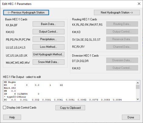
Routing data is entered by selecting an outlet and then selecting the Routing Data button from the Edit HEC-1 Parameters dialog.
Routing name – Enter the defined routing name here.
Combining name – Enter combining name here.
Routing Type – Enter the type of routing being currently used.
- "No Routing (RN)" – Select if there is no routing data attached to the current project.
- "Muskingum-Cunge (RD)" – Define the channel geometry using an eight point cross-section
- Normal Muskingum Cunge parameters – Select to turn on the option to enter parameters.
- L – Channel length.
- S – Channel slope.
- N – Manning's roughness.
- SHAPE: – Characteristic channel shape.
- TRAP – Select this when the channel shape is trapezoidal.
- DEEP – Select this when the channel shape is deep.
- CIRCULAR – Select this when the channel shape is circular.
- WD – Base width of the channel.
- Z – Side slope of channel.
- Defined Cross Section – Select to bring up the Define Cross Section Option in this dialog.
- Enter RC Record – Select to bring up the RC Chennel Record dialog to define Manning and channel data.
- Normal Muskingum Cunge parameters – Select to turn on the option to enter parameters.
- "Kinematic wave (RK)" – Select to define Kinematic Wave routing data.
- L – Channel length.
- S – Channel slope.
- N – Manning's roughness.
- Shape – Characteristic channel shape.
- TRAP – Select this when the channel shape is trapezoidal.
- DEEP – Select this when the channel shape is deep.
- CIRCULAR – Select this when the channel shape is circular.
- WD – Base width of the channel.
- Z – Side slope of channel.
- "Muskingum (RM)" – Select to define Muskingum routing data. It is dependent primarily upon an input weighting factor.
- Compute NSTPS – Select to compute the number of integer steps for the Muskingum routing.
- NSTPS – The number of integer steps for the Muskingum routing.
- AMSK – Muskingum K coefficient in hours for entire reach (measured in hours).
- X – Muskingum x coefficient.
- "Straddler/Stagger (RT)" – Select to define Straddler/ Stagger routing data.
- Compute NSTPS – Select to compute the number of integer steps for the Muskingum routing.
- NSTPS – The number of integer steps for the Muskingum routing.
- AMSK – Muskingum K coefficient in hours for entire reach (measured in hours).
- X – Muskingum x coefficient.
- "Storage (RS)" – Select to define storage data.
- Compute NSTPS – Select to compute the number of integer steps for the Muskingum routing.
- NSTPS – The number of integer steps for the Muskingum routing.
- Type – Define which of the following types is being used in this project.
- STOR – Storage in acre-feet.
- FLOW – Discharge in cfs.
- ELEV – Elevation in feet.
- RSVRIC – This measurement changes depending on the initial condition type that is set. STOR is measured in ac-ft, FLOW is measured in cfs, and ELEV is measured in feet.
- X – Muskingum x coefficient.
- Channel – Long strip of water.
- Reservoir – Stagnent body of water.
- Define – Select to open either the Channel dialog, or the Reservoir dialog and define each.
- "Convex (RV)" – Similar to the Kinematic Wave Routing Method in necessary data entry.
- L – Channel length.
- S – Channel slope.
- N – Manning's roughness.
- Shape – Characteristic channel shape.
- TRAP – Select this when the channel shape is trapezoidal.
- DEEP – Select this when the channel shape is deep.
- CIRCULAR – Select this when the channel shape is circular.
- WD – Base width of the channel.
- Z – Side slope of channel.
Channel Loss – Total water loss of the channel after the computation of three different factors which are listed below.
- QLOSS – Constant channel loss in entire routing in cfs (cms). This value is subtracted from every ordinate of the inflow hydrograph.
- CLOSS – Ratio of remaining flow (after QLOSS) which is lost for entire routing.
- PERCRT – Percolation rate cfs/acre (cu m/sec-acre) for wetted surface area of channel. This option is used in conjunction with storage routing and requires SA or SV/SE records to be defined.
- ELVINV – Average invert elevation of channel L used to compute flow surface area for PERCRT.
Direct input hydrograph (QI) – A hydrograph defined by specific input.
- Define QI – Select to bring up the XY Series Editor dialog.
Observed hydrograph (QO) – A hydrograph defined by specific observations.
- Define QO – Select to bring up the XY Series Editor dialog.
Pattern hydrograph (QP) – A hydrograph defined by specific patterns.
- Define QP – Select to bring up the XY Series Editor dialog.===Outlet Names (KK)===
Since outlets are used for both types (combining and routing) of hydrograph stations in the HEC-1 input file, a separate name for each type of hydrograph must be entered. The name should be six characters or less and correspond to the name used on the KK card to represent the appropriate hydrograph station. By default WMS uses the basin ID number followed by a "R" for the name, but a descriptive name is generally more useful.
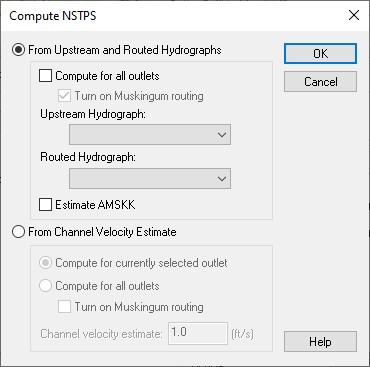
Compute NSTPS Dialog
Accessed by Selecting Compute NSTPS in the HEC-1 Routing Data dialog.
NSTPS is the number of routing sub-reaches used to route the hydrograph in the Muskingum (RM), Straddler Stagger (RT), and Storage (RS) routing methods. To insure the Muskingum method's computational stability and the accuracy of computed hydrograph, the routing reach should be chosen so that:
Where X is the Muskingum weighting factor (0 ≤ X ≤ 0.5), AMSKK is the travel time through the reach in minutes (multiply by 60), and Δt is the computation time interval defined in the HEC-1 Job Control dialog in minutes.
For storage routing, NSTPS is usually about equal to (reach length / average velocity) / Δt, where Δt is described above. Set NSTPS to 1 for a reservoir.
From Upstream and Routed Hydrographs – Select to allow the definition of variables associated with Upstream and Routed Hydrographs.
Compute for all outlets – Select to compute for all outlets.
- Turn on Muskingum routing – Select to apply Muskingum routing.
Upstream Hydrograph – Select to choose an Upstream Hydrograph.
Estimated AMSKK – Select to find the estimated Muskingum k coefficient in hours for entire reach.
For Channel Velocity Estimate – Select to find the estimate for the channel velocity.
Compute for currently selected outlet – Select to compute the outlet that has been chosen.
Compute for all outlets – Select to compute for all outlets.
- Turn on Muskingum routing – Select to apply Muskingum routing.
Channel Velocity Estimate: – An estimation of the channel velocity measured in feet per second.
Muskingum (RM)
The Muskingum method is dependent primarily upon an input weighting factor. The parameters along with short descriptions of their meanings follow:
- NSTPS – The number of integer steps for the Muskingum routing.
- AMSKK – Muskingum K coefficient in hours for entire reach.
- X – Muskingum x coefficient.
Using the basin data computed by WMS when a TIN or DEM is used to delineate the watershed, the AMSKK and NSTPS coefficients can easily be estimated. AMSKK is essentially the travel time for the reach, which can be estimated by noting the length of the stream segment (displayed in the Muskingum Cunge dialog even though it is dimmed) and dividing by an assumed channel velocity (1–5 ft/s would be appropriate for most natural channels). Of course it is necessary to convert the estimated travel times from seconds to hours before entering it into the AMSKK edit field. The NSTPS value is the number of time steps the flood wave is in the channel and can be determined by dividing AMSKK by the computational time step found in the Job Control dialog (again, be sure that units are consistent).
The Muskingum method computes outflow from a reach using the following equation:
where QIN is the inflow to the routing reach in cfs (m3/sec), QOUT is the outflow from the routing reach in cfs (m3/sec), AMSKK is the travel time through the reach in hours, and X is the Muskingum weighting factor (0 ≤ X ≤ 0.5). The routing procedure may be repeated for several subreaches (designated as NSTPS) so the total travel time through the reach is AMSKK.
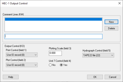
HEC-1 Output Control Dialog
Dialog is accessed by selecting HEC-1 | Edit Parameters... in WMS and then choosing Output Control... from the Edit HEC-1 Parameters dialog.
For each hydrograph station (basin hydrographs, combined hydrographs, and routed hydrographs) different output controls can be specified. This dialog is accessed by selecting the outlet, basin, reservoir, or diversion for which to edit data and then selecting the Output Control dialog button from the Edit HEC-1 Parameters dialog. Entries that can be defined in this dialog are described below.
Comment Lines section – Section that allows comments to be written out.
- New – Select to add a new comment.
- Delete – Select to delete an existing comment.
Output Control (KO)
- Print Control (field 1) – controls how the data collected is printed.
- "Use IO record (O)" – Default setting, prints the entire IO record.
- "Print all output (1,2)" – When selected, prints all output.
- "Print input and summaries" – When selected, it will just print input and summaries of the data.
- "Print input data only (4)" – When selected, it will print the input data only.
- Plot Control (field 2) – Section where plots can be controlled.
- "Use IO record (O)" – Plots are dependant on the IO record.
- "No printer plots (1)" – Select if there are no printer plots.
- "Plot hydrograph (2)" – Select to receive output on the plot hydrograph.
- Plotting Scale (field 3) – Section to specify the plotting scale.
- Unit 7 Control (field 4) – If the unit 7 control should be on select yes, if not select no.
- Hydrograph Control (field 5) – Section designated to control the output of hydrographs.
- "TAPE22 file (22)" – The file read by WMS for the display of hydrographs. This should only be changed to suppress particular hydrographs.
- "TAPE 21 file (21)" – The file used to suppress particular hydrographs.
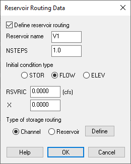
Reservoir Routing Data Dialog
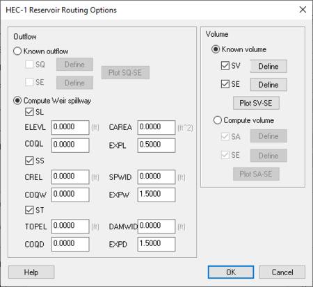
If the reservoir routing option is specified then one method for volume and one method for outflow must be defined.
Reservoirs in HEC-1 can be defined in a few different ways, depending on the storage routing techniques that need to be modeled. The tutorial on creating topologic trees outlines the different methods that can be used to represent reservoirs. The parameters required to define the reservoir are the same in all cases. The main difference is whether the reservoir stands alone by itself or whether the routing option of the outlet is used to define the reservoir.
Define Reservoir Routing – Select to activate the ability to define specific data pertaining to reservoir routing.
- Reservoir Name – Enter the name of the reservoir here.
- NSTEPS – Should be one for Straddler/Stagger method or integer number of routing steps to be used.
- Initial Condition Type – Indicates which type of reservoir is being defined.
- STOR – Storage in acre-feet.
- FLOW – Discharge in cfs.
- ELEV – Elevation in feet.
- RSVRIC – This measurement changes depending on the initial condition type that is set. STOR is measured in ac-ft, FLOW is measured in cfs, and ELEV is measured in feet.
- X – Muskingum x coefficient.
- Type of Storage Routing – Used to specify the type of storage routing being used in the defining of the reservoir data.
- Channel– By selecting this you are associating the storage routing type to be specific to a channel.
- Reservoir– By selecting this you are associating the storage routing type to be specific to a reservoir.
- Define – Upon selecting either Channel or Reservoir as the type of storage routing, select this box to bring up the the Channel Dialog for Channel, or the HEC-1 Reseroir Routing Options Dialog for Reservoir.
- Known volume – Define a known volume (SV) record using the XY Series Editor. Optionally, define the elevations (SE) which correspond to the known volumes.
- Computed volume – By defining an area (SA) elevation (SE) relationship the volume can be computed automatically by HEC-1. Both * records are defined using the XY Series Editor.
If a TIN has been used to define the watershed a storage capacity curve can be generated and the information used to set up the volume/elevation (SV, SE) or area/elevation (SA, SE) data. See Storage Capacity Curves for more information.
The available methods for outflow include:
- Known outflow – Define a known outflow (SQ) record using the XY Series Editor.
- Computed Weir Spillway – A combination of data records are used to define spillway characteristics (SL, SS, ST).
Channel Data
Constant channel losses may be defined by defining values for the RL record. These parameters include the following:
- QLOSS – Constant channel loss in entire routing in cfs (cms). This value is subtracted from every ordinate of the inflow hydrograph.
- CLOSS – Ratio of remaining flow (after QLOSS) which is lost for entire routing. After subtracting QLOSS each inflow hydrograph ordinate is multiplied by (1-CLOSS).
- PERCRT – Percolation rate cfs/acre (cu m/sec-acre) for wetted surface area of channel. This option is used in conjunction with storage routing and requires SA or SV/SE records to be defined.
- ELVINV – Average invert elevation of channel L used to compute flow surface area for PERCRT.
Channel Routing
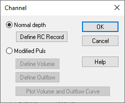
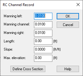
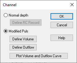
If the channel routing option is specified, the Define button will access a dialog which allows choosing between Normal depth and Modified-Puls methods. If Normal depth is specified, the following parameters must be defined for the RC record.
- Manning's coefficients – Manning roughness coefficients for the channel and left and right overbanks.
- Length – The length of the river reach.
- Slope – The slope of the river reach.
- Max Elevation – The maximum elevation for which storage and outflow values are to be computed.
In addition to these parameters an eight point cross section must be defined using the XY Series Editor. The first two points define the left overbank, the third point defines the left bank, the fourth and fifth points define the channel itself, the sixth point defines the right bank, and the last two points define the right overbank.
If the modified-Puls method is chosen the volume (SV) outflow (SQ) relationship must be defined. Both records are defined using the XY Series Editor.
Hydrographs
Direct Input Hydrograph (QI) – Hydrographs can be input directly using the QI record, and then routed downstream using the different routing options. To do this, select the Direct Input Hydrograph option and define the QI record using the XY Series Editor.
Pattern Hydrograph (QP) – This option is used to input a pattern hydrograph for an optimization job (OR record). A QP hydrograph can be used in conjunction with a QI and QO hydrograph to optimize routing parameters. This hydrograph can be input by selecting the check box and then defining the hydrograph using the XY Series Editor.
Related Topics
| [hide] WMS – Watershed Modeling System | ||
|---|---|---|
| Modules: | Terrain Data • Drainage • Map • Hydrologic Modeling • River • GIS • 2D Grid • 2D Scatter |  |
| Models: | CE-QUAL-W2 • GSSHA • HEC-1 • HEC-HMS • HEC-RAS • HSPF • MODRAT • NSS • OC Hydrograph • OC Rational • Rational • River Tools • Storm Drain • SMPDBK • SWMM • TR-20 • TR-55 | |
| Toolbars: | Modules • Macros • Units • Digitize • Static Tools • Dynamic Tools • Drawing • Get Data Tools | |
| Aquaveo | ||
