WMS:Project Explorer Contents for Terrain Data Module
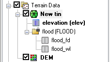
In the Terrain Data module, TINs and DEMs are listed in the Project Explorer. A toggle is next to each object; the toggle controls the visibility. The display is automatically updated when the toggle is checked or unchecked.
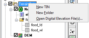
Right-clicking on the main Terrain Data folder ![]() allows creating a New folder or TIN. Because TINs can be created by digitizing in WMS, a new, blank TIN can be created. However, DEMs are only created by opening a DEM file type. If neither a TIN nor a DEM exists, then a Reprojection can be performed on any existing terrain data. There is also an option to open a digital elevation file. Opening a digital elevation file using this option will open an elevation grid as a WMS DEM.
allows creating a New folder or TIN. Because TINs can be created by digitizing in WMS, a new, blank TIN can be created. However, DEMs are only created by opening a DEM file type. If neither a TIN nor a DEM exists, then a Reprojection can be performed on any existing terrain data. There is also an option to open a digital elevation file. Opening a digital elevation file using this option will open an elevation grid as a WMS DEM.
- New Tin: Creates a new TIN from the background elevation.
- New Folder: Creates a new folder in the Project Explorer under the selected item in the tree.
- Open Digital Elevation File(s): Brings up the Select DEM File(s) dialog.
TIN Object Right-Click Menu
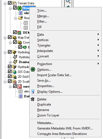
Right-clicking on a TIN ![]() allows selecting any of the TIN processing or visualization options in WMS. The commands in this menu are as follows:
allows selecting any of the TIN processing or visualization options in WMS. The commands in this menu are as follows:
- Trim: Opens the Polygon Selection Options dialog.
- Merge: Opens the Merge TINs dialog.
- Filter: Brings up the Maximum filter angle dialog.
- Fill: Triangulates a selected polygon and merges it with the original TIN.
- Data: A submenu for adjusting datasets in the TIN. It contains the following commands:
- Calculator: Launches the Data Calculator dialog for modifying or creating datasets in the TIN.
- Smooth Dataset: Rounds the data values and creates a new dataset under the TIN with the smoothed values.
- Map Elevation
- Film Loop: Starts the Film Loop Setup dialog for creating a animation from the TIN.
- Vertices: A submenu for adjusting vertices in the TIN. It contains the following commands:
- Lock/Unlock: Selected vertices can be locked to prevent them from being dragged or edited.
- Delete Duplicates: Removes vertices that duplicate the same xy location as another vertex.
- Smooth Pits: Adjusts the elevations of pits in order to remove them.
- Transform: Used to move TIN vertices according to a specified transformation.
- Triangles: A submenu for triangulatin options in the TIN. It contains the following commands:
- Triangulate: Triangulates the vertices of the TIN.
- Insert Breaklines:
- Optimization Triangulation: Optimizes triangulation according to criteria specified in the TIN Options dialog.
- Check Long/Thin Triangles:
- Remove Flat Triangles: Attempts to eliminate flat triangles on a TIN.
- Interpolate: A submenu for interpolating the TIN data to another module or TIN. It contains the following commands:
- To 2D Grid
- To TIN
- To Feature Objects
- Convert: A submenu for converting the TIN data to another module or DEM. It contains the following commands:
- TIN Contours→Feature: Converts the current linear contours from the TIN to a series of feature arcs which could then be exported as a shapefile.
- TIN Boundary→Feature: Creates a boundary feature polygon from the vertices on the boundary of the TIN.
- TIN→2D Scatter Points: Creates a 2D scatter point set from the TIN.
- TIN→DEM: Creates a DEM from the TIN.
- Projection: A submenu for changing the coordinate system of the TIN. It contains the following commands:
- Projection
- Set as Display Projection
- Reproject
- Transform
- Options: Brings up the TIN Options dialog.
- Import Scalar Dataset: Imports a scalar dataset by first selecting the type of scalar dataset to import and then launching the Open dialog.
- Save As: Used to designate the path and prefix file name for saving a TIN.
- Properties: Brings up the Properties window for the TIN.
- Display Options: Brings up the Display Options dialog.
- Delete: Removes the TIN from the project.
- Duplicate: Creates a copy of the TIN.
- Rename: Lets the name of the TIN be changed in the Project Explorer.
- Zoom To Layer: Will resize the TIN data so it fills the Graphics Window.
- Metadata: Brings up a Metadata dialog.
- Generate Metadata XML From XMDF
- Compute Area Between Elevations
A TIN by default has a single elevation dataset, but additional datasets can be created, such as flood depth and water surface elevation datasets when delineating a floodplain. For more information on datasets see Datasets.
TIN Dataset Right-Click Menu
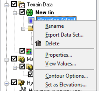
Right-clicking on a dataset of a TIN allows the following options:
- Rename: Changes the name of the dataset in the Project Explorer.
- Export Dataset: Selects the file format and save the dataset.
- Delete: Removes the dataset from the TIN.
- Properties: Brings up the Properties window for the dataset.
- View Values: Opens the Edit Dataset Values dialog.
- Contour Options: Brings up the Contour Options dialog.
- Set as Elevations: Assigns the dataset as the elevation dataset for the TIN.
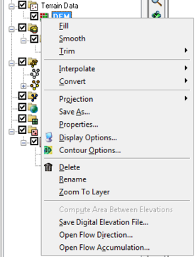
DEM Object Right-Click Menu
Right-clicking on a DEM ![]() allows selecting any of the DEM processing or visualization options in WMS. All DEMs are created by either reading a file or converting from another data object, such as a TIN or from raster GIS data. If multiple DEMs exist, these DEMs can be selected and merged together into a single DEM. There is only one active DEM. This active DEM is used for watershed delineation and for all other processes that require elevation data in WMS. In WMS 10.1 and later, a DEM raster can be cropped with a freehand polygon by selecting the Trim | Polygon option.
allows selecting any of the DEM processing or visualization options in WMS. All DEMs are created by either reading a file or converting from another data object, such as a TIN or from raster GIS data. If multiple DEMs exist, these DEMs can be selected and merged together into a single DEM. There is only one active DEM. This active DEM is used for watershed delineation and for all other processes that require elevation data in WMS. In WMS 10.1 and later, a DEM raster can be cropped with a freehand polygon by selecting the Trim | Polygon option.
- Fill:Triangulates a selected polygon and merges it with the original DEM.
- Smooth:Rounds the data values and creates a new dataset under the DEM with the smoothed values.
- Trim: Opens the Polygon Selection Options dialog.
- Polygon: Brings up the Polygon Selection Options dialog.
- Elevation: Brings up the DEM Trim by Elevation dialog.
- Interpolate:
- To 2D Grid:
- To TIN:
- To Feature Objects:
- Convert:
- DEM Contours→Feature: Coverts contours to feature object, and converts nodes to vertices.
- DEM→TIN:
- All: Brings up the DEM Conversion Options dialog.
- Filtered:
- Projection:
- Projection: Brings up the Projection dialog.
- Set As Display Projection:
- Reproject: Brings up the Reproject Object dialog.
- Transform: Brings up the Transform DEM dialog.
- Save As: Used to designate the path and prefix file name for saving a DEM.
- Properties: Brings up the Properties window for the DEM.
- Display Options: Brings up the Display Options dialog.
- Contour Options: Brings up the elevation (elev) Contour Options.
- Delete: Removes the DEM from the project.
- Rename: Lets the name of the DEM be changed in the Project Explorer.
- Zoom To Layer: Will resize the DEM data so it fills the Graphics Window.
- Compute Area Between Elevations:
- Save Digital Elevation File: Brings up the Save As dialog.
- Open Flow Direction: Brings up the Open dialog.
- Open Flow Accumulation: Brings up the Open dialog.
Related Topics
| [hide] WMS – Watershed Modeling System | ||
|---|---|---|
| Modules: | Terrain Data • Drainage • Map • Hydrologic Modeling • River • GIS • 2D Grid • 2D Scatter |  |
| Models: | CE-QUAL-W2 • GSSHA • HEC-1 • HEC-HMS • HEC-RAS • HSPF • MODRAT • NSS • OC Hydrograph • OC Rational • Rational • River Tools • Storm Drain • SMPDBK • SWMM • TR-20 • TR-55 | |
| Toolbars: | Modules • Macros • Units • Digitize • Static Tools • Dynamic Tools • Drawing • Get Data Tools | |
| Aquaveo | ||
