WMS:Feature Object Guidelines: Difference between revisions
No edit summary |
|||
| (One intermediate revision by the same user not shown) | |||
| Line 15: | Line 15: | ||
:2) a scanned TIFF image that can be read into WMS and used as a background map. | :2) a scanned TIFF image that can be read into WMS and used as a background map. | ||
[[Image:feature_object_guidelines_1.jpg]] | :[[Image:feature_object_guidelines_1.jpg]] | ||
===3. Construct Feature Object Topology=== | ===3. Construct Feature Object Topology=== | ||
| Line 27: | Line 27: | ||
An important point to remember in WMS is that lines used to define a stream network have direction. For each line (arc) there is a beginning and an ending node and “flow” along the line is defined in this direction. When interactively creating lines in WMS, always create streams from downstream to upstream. If importing a set of lines that has been previously created by another program, it is possible that the order does not match what is required by WMS. The [[WMS:Feature Objects Menu#Reorder Streams|Reorder Streams]] command in the '''Feature Objects''' menu (Map module) can be used to properly order the incoming lines so that they can be converted to streams. | An important point to remember in WMS is that lines used to define a stream network have direction. For each line (arc) there is a beginning and an ending node and “flow” along the line is defined in this direction. When interactively creating lines in WMS, always create streams from downstream to upstream. If importing a set of lines that has been previously created by another program, it is possible that the order does not match what is required by WMS. The [[WMS:Feature Objects Menu#Reorder Streams|Reorder Streams]] command in the '''Feature Objects''' menu (Map module) can be used to properly order the incoming lines so that they can be converted to streams. | ||
[[Image:feature_object_guidelines_2.jpg]] | :[[Image:feature_object_guidelines_2.jpg]] | ||
===4. Define the Hydrologic Model=== | ===4. Define the Hydrologic Model=== | ||
Latest revision as of 16:00, 26 October 2017
GIS vector data includes points, lines, and polygons that are used in WMS to represent basins, streams, and key points such as outlets or culverts. In WMS we refer to this GIS data as Feature Objects, and tools for using them are included in the Map Module. Feature object data can be used by itself to create a watershed model for hydrologic analysis or as a companion in the development of watershed models with TINs and DEMs.
Many times it is not practical to obtain digital elevation data and perform an automated watershed characterization prior to setting up a hydrologic model. Watershed and sub-basin boundaries may already be known and stored as part of a GIS or CAD database, or it may be straight-forward to trace an existing map to define streams and basins. With WMS, properly structured hydrologic models can be created automatically from points, lines, and polygons. Since these data are often already developed and stored in a GIS, importing from ARC/INFO® and ArcView®, or DXF files is easily done.
The following are the basic steps taken to create watershed models from GIS data within WMS.
1. Obtain a Map or Already Developed GIS or CAD Data
The first step is to obtain a map that defines the streams and basins which will be modeled. If such a map already exists digitally as a CAD drawing or as part of a GIS database then it can be imported directly and the next step can be skipped.
2. Digitize the Map
The map can then be digitized using a tablet and standard digitizing software outside of WMS and then imported as a CAD or GIS file, or it can be created using "heads up," or "on-screen digitizing" inside of WMS. In order to do heads up digitizing, complete one of two things:
- 1) digital elevation data that can be contoured by WMS
- 2) a scanned TIFF image that can be read into WMS and used as a background map.
3. Construct Feature Object Topology
The points and lines must be assigned the right attribute types, and the polygons for sub-basins constructed from the lines.
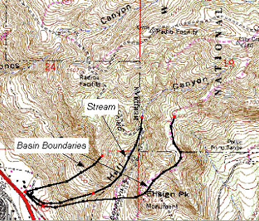
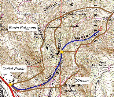
If using data already developed in a GIS then some editing may be needed. This will depend on how well the data being imported matches with the required data for watershed model development. In WMS three primary layers as illustrated below : 1) A point layer representing the watershed outlet and any sub-basin outlet or confluence points, 2) a line layer representing a stream network, and 3) a polygon layer representing watershed boundaries.
If all three layers exist then construction of the watershed model topology can proceed, but if one or more of the layers are absent, they must be created manually from within WMS. For example if the the project only has a file that contained sub-basin boundaries, digitize the stream network and define the outlet locations of the sub-basins.
An important point to remember in WMS is that lines used to define a stream network have direction. For each line (arc) there is a beginning and an ending node and “flow” along the line is defined in this direction. When interactively creating lines in WMS, always create streams from downstream to upstream. If importing a set of lines that has been previously created by another program, it is possible that the order does not match what is required by WMS. The Reorder Streams command in the Feature Objects menu (Map module) can be used to properly order the incoming lines so that they can be converted to streams.
4. Define the Hydrologic Model
Once the watershed model representation has been created, data defining a specific hydrologic model can be entered through a series of dialogs. Since WMS allows for all hydrologic modeling input to be defined separate from any digital terrain data, it is not required that the watershed model developed with feature objects be to scale. Area and length parameters can simply be manually defined using the model interface. The figure below shows how a topologic model is automatically created from point, line, and polygon feature object data.
Related Topics
WMS – Watershed Modeling System | ||
|---|---|---|
| Modules: | Terrain Data • Drainage • Map • Hydrologic Modeling • River • GIS • 2D Grid • 2D Scatter |  |
| Models: | CE-QUAL-W2 • GSSHA • HEC-1 • HEC-HMS • HEC-RAS • HSPF • MODRAT • NSS • OC Hydrograph • OC Rational • Rational • River Tools • Storm Drain • SMPDBK • SWMM • TR-20 • TR-55 | |
| Toolbars: | Modules • Macros • Units • Digitize • Static Tools • Dynamic Tools • Drawing • Get Data Tools | |
| Aquaveo | ||


