WMS:Channel Calculator: Difference between revisions
No edit summary |
No edit summary |
||
| (12 intermediate revisions by 2 users not shown) | |||
| Line 2: | Line 2: | ||
WMS, beginning in version 9.1, uses ''Hydraulic Toolbox'' to perform the channel calculations. It is useful to be able to analyze the conveyance and other properties of channels using Manning’s equation. The first dialog of the ''Channel Calculator'', shows tools for slope, cross sections, launching Hydraulic Toolbox's channel calculator, and creating a stage point. | WMS, beginning in version 9.1, uses ''Hydraulic Toolbox'' to perform the channel calculations. It is useful to be able to analyze the conveyance and other properties of channels using Manning’s equation. The first dialog of the ''Channel Calculator'', shows tools for slope, cross sections, launching Hydraulic Toolbox's channel calculator, and creating a stage point. | ||
Use the measure tool to determine the slope across a specified arc, as long as the user has elevation data loaded into WMS then turn on cross sections. The image showing channel geometry becomes updated with the selected cross section, and the Z scale can be adjusted to better view the channel. | |||
The ''Reach name'', ''Cross Section ID'', and ''station'' are all updated when a cross section is selected. | |||
'''Select Cross Section''' – Select the channel by selecting this. | |||
'''Create Stage Point''' – Is used floodplain delineation, which is described below. | |||
'''Launch Channel Calculator''' – Will show the ''Channel Analysis'' from ''Hydraulic Toolbox'' with any information entered in WMS. | |||
[[Image:WMSChannelCalculator.png|400 px]] | [[Image:WMSChannelCalculator.png|400 px]] | ||
''Channels Calculator'' – Allows for the definition of rectangular, trapezoidal, triangular, circular, and user defined cross-sectional channels. | |||
Once channel input geometry is specified, either depth or flow can be computed after supplying a value for the other. | Once channel input geometry is specified, either depth or flow can be computed after supplying a value for the other. | ||
User | User defined cross sections are defined from a cross-section coverage and can be interpolated from a background TIN or DEM. | ||
All calculations (except Froude Number) are made using Manning’s Equation: | All calculations (except Froude Number) are made using Manning’s Equation: | ||
| Line 24: | Line 26: | ||
where: | where: | ||
''Q'' – Flow in cfs | |||
''n'' – Manning’s roughness | |||
''A'' – Cross section area of flow | |||
''R'' – Hydraulic radius | |||
''S'' – Slope | |||
The Froude Number is computed from: | The Froude Number is computed from: | ||
| Line 40: | Line 42: | ||
where: | where: | ||
< | ''N<sub>F</sub>'' – Froude Number | ||
''V'' – Velocity | |||
''g'' – acceleration due to gravity | |||
''y'' – equivalent depth of flow for a rectangular channel. | |||
The equivalent depth of flow for a rectangular channel is computed by dividing the cross sectional area of flow by the top width of the water surface. | The equivalent depth of flow for a rectangular channel is computed by dividing the cross-sectional area of flow by the top width of the water surface. | ||
== | ==Floodplain Delineation Computations== | ||
Besides the ability to analyze the hydraulic properties of channels, results can be used to perform basic | Besides the ability to analyze the hydraulic properties of channels, results can be used to perform basic floodplain delineation. If there are computed flowrates from one of the supported hydrologic models, estimate stage or water surface elevation using the channel calculator. | ||
When computing the depth using a cross section arc, | When computing the depth using a cross section arc, have a new scatter point created along the arc that contains the water surface elevation (depth calculated plus the lowest elevation of the cross section). If a centerline arc in a [[WMS:1D-HYD Centerline Coverage Type|1D-Hydraulic Centerline]] coverage exists the new scatter point will be created at the intersection of the centerline and cross section when selecting the '''Create Stage Point''' button. A set of scattered points create in this fashion can be used to perform a floodplain delineation. The [[WMS:Interpolating Hydraulic Model Results|scatter points should be interpolated along the cross sections and centerlines]] prior to delineating the floodplain in order to provide the delineation algorithm with more points so that the interpolation functions work better. Some studies would require a more complete hydraulic analysis [[WMS:Hydraulic Modeling|using a 1D (HEC-RAS) hydraulic modeling program]]. | ||
==Related Topics== | ==Related Topics== | ||
| Line 60: | Line 62: | ||
* [[WMS:Preparing Stage Data|Preparing Stage Data for Floodplain Delineation]] | * [[WMS:Preparing Stage Data|Preparing Stage Data for Floodplain Delineation]] | ||
* [[WMS:Interpolating Hydraulic Model Results|Interpolating Stages]] | * [[WMS:Interpolating Hydraulic Model Results|Interpolating Stages]] | ||
* [[WMS:Overview of | * [[WMS:Overview of Floodplain Delineation|Floodplain Delineation]] | ||
* [[WMS:Hydraulic Modeling | * [[WMS:Hydraulic Modeling|Hydraulic Modeling]] | ||
* [[WMS:Hydraulic Toolbox|Hydraulic Toolbox]] | * [[WMS:Hydraulic Toolbox|Hydraulic Toolbox]] | ||
| Line 68: | Line 70: | ||
[[Category:Calculators|C]] | [[Category:Calculators|C]] | ||
[[Category:WMS Dialogs|C]] | [[Category:WMS Dialogs|C]] | ||
[[Category:Equations| | [[Category:Equations|Channel]] | ||
Latest revision as of 21:57, 4 May 2020
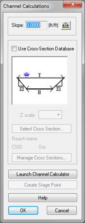
WMS, beginning in version 9.1, uses Hydraulic Toolbox to perform the channel calculations. It is useful to be able to analyze the conveyance and other properties of channels using Manning’s equation. The first dialog of the Channel Calculator, shows tools for slope, cross sections, launching Hydraulic Toolbox's channel calculator, and creating a stage point.
Use the measure tool to determine the slope across a specified arc, as long as the user has elevation data loaded into WMS then turn on cross sections. The image showing channel geometry becomes updated with the selected cross section, and the Z scale can be adjusted to better view the channel.
The Reach name, Cross Section ID, and station are all updated when a cross section is selected.
Select Cross Section – Select the channel by selecting this.
Create Stage Point – Is used floodplain delineation, which is described below.
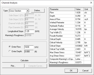
Launch Channel Calculator – Will show the Channel Analysis from Hydraulic Toolbox with any information entered in WMS.
Channels Calculator – Allows for the definition of rectangular, trapezoidal, triangular, circular, and user defined cross-sectional channels.
Once channel input geometry is specified, either depth or flow can be computed after supplying a value for the other.
User defined cross sections are defined from a cross-section coverage and can be interpolated from a background TIN or DEM.
All calculations (except Froude Number) are made using Manning’s Equation:
where:
Q – Flow in cfs
n – Manning’s roughness
A – Cross section area of flow
R – Hydraulic radius
S – Slope
The Froude Number is computed from:
where:
NF – Froude Number
V – Velocity
g – acceleration due to gravity
y – equivalent depth of flow for a rectangular channel.
The equivalent depth of flow for a rectangular channel is computed by dividing the cross-sectional area of flow by the top width of the water surface.
Floodplain Delineation Computations
Besides the ability to analyze the hydraulic properties of channels, results can be used to perform basic floodplain delineation. If there are computed flowrates from one of the supported hydrologic models, estimate stage or water surface elevation using the channel calculator.
When computing the depth using a cross section arc, have a new scatter point created along the arc that contains the water surface elevation (depth calculated plus the lowest elevation of the cross section). If a centerline arc in a 1D-Hydraulic Centerline coverage exists the new scatter point will be created at the intersection of the centerline and cross section when selecting the Create Stage Point button. A set of scattered points create in this fashion can be used to perform a floodplain delineation. The scatter points should be interpolated along the cross sections and centerlines prior to delineating the floodplain in order to provide the delineation algorithm with more points so that the interpolation functions work better. Some studies would require a more complete hydraulic analysis using a 1D (HEC-RAS) hydraulic modeling program.
Related Topics
- Hydrologic/Hydraulic Calculators
- Preparing Stage Data for Floodplain Delineation
- Interpolating Stages
- Floodplain Delineation
- Hydraulic Modeling
- Hydraulic Toolbox
WMS – Watershed Modeling System | ||
|---|---|---|
| Modules: | Terrain Data • Drainage • Map • Hydrologic Modeling • River • GIS • 2D Grid • 2D Scatter |  |
| Models: | CE-QUAL-W2 • GSSHA • HEC-1 • HEC-HMS • HEC-RAS • HSPF • MODRAT • NSS • OC Hydrograph • OC Rational • Rational • River Tools • Storm Drain • SMPDBK • SWMM • TR-20 • TR-55 | |
| Toolbars: | Modules • Macros • Units • Digitize • Static Tools • Dynamic Tools • Drawing • Get Data Tools | |
| Aquaveo | ||


