WMS:Coverages: Difference between revisions
No edit summary |
|||
| (7 intermediate revisions by 3 users not shown) | |||
| Line 1: | Line 1: | ||
Feature objects in the Map module are grouped into coverages. A coverage is similar to a layer or level in a CAD drawing | Feature objects in the Map module are grouped into coverages. A coverage is similar to a layer or level in a CAD drawing. Each coverage represents a particular set of information. For example, one coverage could be used to define drainage boundaries and another coverage could be used to define land use or soil zones. These objects could not be included in a single coverage since polygons within a coverage are not allowed to overlap. | ||
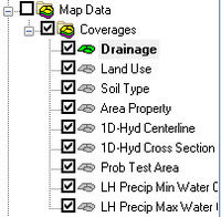
Coverages are managed using the Project Explorer. Coverages can be organized into folders and moved once they are created. When WMS is first launched the default coverage is a drainage coverage. When multiple coverages are created, one coverage is designated the "active" coverage. New feature objects are always added to the active coverage and only objects in the active coverage can be edited. The figure below shows several coverages in the Project Explorer. The active coverage is displayed with a color icon and bold text. A coverage is made the active coverage by selecting it from the Project Explorer. In some cases it is useful to hide some or all of the coverages. The visibility of a coverage is controlled using the check box next to the coverage in the Project Explorer. | Coverages are managed using the Project Explorer. Coverages can be organized into folders and moved once they are created. When WMS is first launched the default coverage is a drainage coverage. When multiple coverages are created, one coverage is designated the "active" coverage. New feature objects are always added to the active coverage and only objects in the active coverage can be edited. The figure below shows several coverages in the Project Explorer. The active coverage is displayed with a color icon and bold text. A coverage is made the active coverage by selecting it from the Project Explorer. In some cases it is useful to hide some or all of the coverages. The visibility of a coverage is controlled using the check box next to the coverage in the Project Explorer. | ||
| Line 24: | Line 24: | ||
* [[WMS:1D-HYD Centerline Coverage Type|1D-HYD Centerline]] | * [[WMS:1D-HYD Centerline Coverage Type|1D-HYD Centerline]] | ||
* [[WMS:1D-HYD Cross | * [[WMS:1D-HYD Cross Section Coverage Type|1D-HYD Cross Section]] | ||
* [[WMS:Area Property Coverage|Area Property]] | * [[WMS:Area Property Coverage|Area Property]] | ||
* [[WMS:CE-QUAL-W2|CE-QUAL-W2 Branch]] | * [[WMS:CE-QUAL-W2|CE-QUAL-W2 Branch]] | ||
* [[WMS:CE-QUAL-W2|CE-QUAL-W2 Segments]] | * [[WMS:CE-QUAL-W2|CE-QUAL-W2 Segments]] | ||
* [[WMS:Drainage|Drainage]] | * [[WMS:Drainage|Drainage]] | ||
* [[WMS:Flood Barrier|Flood Barrier]] | * [[WMS:Flood Barrier|Flood Barrier]] | ||
* '''Flood Extent''' – A flood extent coverage is created from a [[WMS:Delineate Floodplain|flood delineation dataset]] and contains polygons showing inundated limits or differences in inundation limits between two different floodplain delineation scenarios. See [[WMS:Flood Extent|Flood Extent]] for more information. | * '''Flood Extent''' – A flood extent coverage is created from a [[WMS:Delineate Floodplain|flood delineation dataset]] and contains polygons showing inundated limits or differences in inundation limits between two different floodplain delineation scenarios. See [[WMS:Flood Extent|Flood Extent]] for more information. | ||
* [[WMS:Map Flood|Floodplain Mapping]] – Contains flood map extends generated from the Map Flood tool. | |||
* [[WMS:General Coverage|General]] | * [[WMS:General Coverage|General]] | ||
* [[WMS:GSSHA|GSSHA]] | |||
* [[WMS:GSSHA Storm Drain|GSSHA Storm Drain]] | |||
* [[HY8:Culvert Type|HY-8 Culvert]] | |||
* [[WMS:Land Use Coverage|Land Use]] | * [[WMS:Land Use Coverage|Land Use]] | ||
* '''MODRAT DPA Zone''' – This coverage type is used to delineate the Debris Production Area used in a MODRAT simulation. | * '''MODRAT DPA Zone''' – This coverage type is used to delineate the Debris Production Area used in a MODRAT simulation. | ||
* [[WMS:NSS Region Coverage|NSS Region]] | * [[WMS:NSS Region Coverage|NSS Region]] | ||
* [[WMS:Rain Gage|Rain Gage]] | * [[WMS:Rain Gage|Rain Gage]] | ||
* '''Rainfall Zone''' – The rainfall zone coverage is used to map MODRAT rainfall zones for the purpose of developing a MODRAT simulations. These zones correspond to the lettered zones (A-K) and are not a part of the aerial distributed rainfall grid simulations. | * '''Rainfall Zone''' – The rainfall zone coverage is used to map MODRAT rainfall zones for the purpose of developing a MODRAT simulations. These zones correspond to the lettered zones (A-K) and are not a part of the aerial distributed rainfall grid simulations. | ||
* '''Runoff Coefficient''' – The Runoff Coefficient coverage is used in the same | * '''Runoff Coefficient''' – The Runoff Coefficient coverage is used in the same way as the land use coverage, except that rather than defining a land use type, a floating point runoff coefficient can be entered for each polygon. Composite runoff coefficients (C values for the rational method or CN values for the SCS method) can then be computed using the '''Compute GIS Attributes''' command in the ''Calculators'' menu of the Hydrologic Modeling module. | ||
* [[WMS:Soil|Soil]] | * '''Sanitary Sewer''' | ||
* [[WMS:Soil Type Coverage|Soil]] | |||
* [[WMS:Storm Drain|Storm Drain]] | * [[WMS:Storm Drain|Storm Drain]] | ||
* [[WMS:Time Computation|Time Computation]] | * [[WMS:Time Computation|Time Computation]] | ||
* '''Water Distribution''' | |||
==Related Topics== | ==Related Topics== | ||
Latest revision as of 19:44, 8 May 2023
Feature objects in the Map module are grouped into coverages. A coverage is similar to a layer or level in a CAD drawing. Each coverage represents a particular set of information. For example, one coverage could be used to define drainage boundaries and another coverage could be used to define land use or soil zones. These objects could not be included in a single coverage since polygons within a coverage are not allowed to overlap.
Coverages are managed using the Project Explorer. Coverages can be organized into folders and moved once they are created. When WMS is first launched the default coverage is a drainage coverage. When multiple coverages are created, one coverage is designated the "active" coverage. New feature objects are always added to the active coverage and only objects in the active coverage can be edited. The figure below shows several coverages in the Project Explorer. The active coverage is displayed with a color icon and bold text. A coverage is made the active coverage by selecting it from the Project Explorer. In some cases it is useful to hide some or all of the coverages. The visibility of a coverage is controlled using the check box next to the coverage in the Project Explorer.
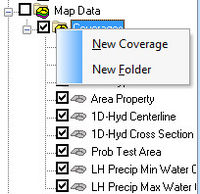
A new coverage can be created by right-clicking on a folder and selecting the New Coverage command in the pop-up menu.
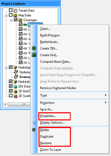
Right-clicking on a coverage bring up a menu with the following options: Delete, Duplicate, Rename, and Properties.
The Delete command will remove the selected coverage. The Duplicate command makes a copy of the selected coverage. The Rename command allows changing the coverage name.
The Properties command brings up the Coverage Properties dialog. The coverage properties dialog allows specifying what the coverage type is, its default elevation (mostly used for displaying and overlaying) and change the name (although the name of the coverage can also be changed from the Project Explorer in the same fashion as changing a name in a typical Windows Explorer.
See the article Coordinate Conversions for information about the Coordinate Conversion command.
Coverage Types
Each coverage is assigned a coverage type that controls which set of attributes are associated with the coverage. The appropriate type for a coverage depends on the intended use of the coverage. The available types are as follows:
- 1D-HYD Centerline
- 1D-HYD Cross Section
- Area Property
- CE-QUAL-W2 Branch
- CE-QUAL-W2 Segments
- Drainage
- Flood Barrier
- Flood Extent – A flood extent coverage is created from a flood delineation dataset and contains polygons showing inundated limits or differences in inundation limits between two different floodplain delineation scenarios. See Flood Extent for more information.
- Floodplain Mapping – Contains flood map extends generated from the Map Flood tool.
- General
- GSSHA
- GSSHA Storm Drain
- HY-8 Culvert
- Land Use
- MODRAT DPA Zone – This coverage type is used to delineate the Debris Production Area used in a MODRAT simulation.
- NSS Region
- Rain Gage
- Rainfall Zone – The rainfall zone coverage is used to map MODRAT rainfall zones for the purpose of developing a MODRAT simulations. These zones correspond to the lettered zones (A-K) and are not a part of the aerial distributed rainfall grid simulations.
- Runoff Coefficient – The Runoff Coefficient coverage is used in the same way as the land use coverage, except that rather than defining a land use type, a floating point runoff coefficient can be entered for each polygon. Composite runoff coefficients (C values for the rational method or CN values for the SCS method) can then be computed using the Compute GIS Attributes command in the Calculators menu of the Hydrologic Modeling module.
- Sanitary Sewer
- Soil
- Storm Drain
- Time Computation
- Water Distribution
Related Topics
WMS – Watershed Modeling System | ||
|---|---|---|
| Modules: | Terrain Data • Drainage • Map • Hydrologic Modeling • River • GIS • 2D Grid • 2D Scatter |  |
| Models: | CE-QUAL-W2 • GSSHA • HEC-1 • HEC-HMS • HEC-RAS • HSPF • MODRAT • NSS • OC Hydrograph • OC Rational • Rational • River Tools • Storm Drain • SMPDBK • SWMM • TR-20 • TR-55 | |
| Toolbars: | Modules • Macros • Units • Digitize • Static Tools • Dynamic Tools • Drawing • Get Data Tools | |
| Aquaveo | ||


