GMS:Coverages: Difference between revisions
From XMS Wiki
Jump to navigationJump to search
No edit summary |
|||
| (53 intermediate revisions by 5 users not shown) | |||
| Line 1: | Line 1: | ||
{{Map links}} | {{Map links}} | ||
[[GMS:Feature Objects|Feature | __TOC__ | ||
[[GMS:Feature Objects|Feature objects]] in the Map module are grouped into coverages. Coverages are grouped into [[GMS:Conceptual Model|conceptual models]]. | |||
{{only in print|[[Image:Tree_Map.gif|frame|right|175px]]}} | |||
A coverage is similar to a layer in a CAD drawing. Each coverage represents a particular set of information. For example, one coverage could be used to define recharge zones and another coverage could be used to define zones of hydraulic conductivity. These objects could not be included in a single coverage since polygons within a coverage are not allowed to overlap and recharge zones will typically overlap hydraulic conductivity zones. | |||
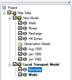
Coverages are managed using the [[GMS:The GMS Window|Project Explorer]]. Coverages are organized below conceptual models. When GMS is first launched, no coverage exists. If no coverage exists and the user creates [[GMS:Feature Objects|feature objects]] then a new coverage will automatically be created. When multiple coverages are created, one coverage is designated the "active" coverage. New feature objects are always added to the active coverage and only objects in the active coverage can be edited. The figure below shows several coverages in the [[GMS:Project Explorer|Project Explorer]]. The active coverage is displayed with a color icon [[File:Coverage Active Icon.svg|16 px]] and bold text. Inactive coverages will have a grayed out icon [[File:Coverage Inactive Icon.svg|16 px]]. A coverage is made the active coverage by selecting it from the Project Explorer. In some cases it is useful to hide some or all of the coverages. The visibility of a coverage is controlled using the check box next to the coverage in the Project Explorer. | |||
{{Anchor|New Coverage}}A new coverage can be created by right-clicking on a folder or conceptual model and selecting the '''New Coverage''' command in the pop-up menu. | |||
{{hide in print|[[Image:Tree_Map.png|thumb|none|240 px|Example of the tree map in the Project Explorer]]}} | |||
==Coverage Right-Click Commands== | |||
Right-clicking on a coverage brings up a menu with the following options: | |||
*'''Delete''' – Removes the selected coverage from the GMS project. Once deleted the coverage will have to be either loaded into GMS again if it came from a file or the coverage will have to be rebuilt. | |||
*'''Duplicate''' – Creates a copy of the selected coverage in the Project Explorer. The duplicate coverage will have the word "Copy of..." affixed to the name of the copied coverage. Additional duplicates will have a number affixed to the name if the copied coverage is not renamed. | |||
*'''Rename''' – Assigns a new name to the selected coverage. | |||
*'''Coverage Setup''' – Brings up the ''Coverage Setup'' dialog. | |||
*'''Attribute Table''' – Brings up the ''Attribute Table'' dialog. | |||
*''Map To'' submenu | |||
*'''Transform''' | |||
*'''Export''' | |||
*'''Properties''' | |||
== Coverage Setup == | |||
[[File:CoverageSetup.png|thumb|450 px|Example of the ''Coverage Setup'' dialog]] | |||
The '''Coverage Setup''' command brings up the ''Coverage Setup'' dialog. This dialog controls the properties that are assigned to feature objects. The feature object properties have been divided into 3 general categories: ''Sources/Sinks/BCs'', ''Areal Properties'', and ''Observation Points''. Under the ''Sources/Sinks/BCs'' the user can select which source/sinks he would like to include in the coverage (like wells, rivers, drains, etc). ''Areal Properties'' includes recharge, ET, hydraulic conductivity, and other properties that are assigned to polygonal zones. ''Observation Points'' control which datasets have associated observation data. | |||
=== Feature Object Properties Categories === | |||
{|class="mw-collapsible mw-collapsed" style="width:50%; border:1px solid #D0E0FF; margin-bottom:0.4em;" | |||
|- | |||
!style="text-align:left;"| Sources/Sinks/BCs | |||
|- | |||
| | |||
*''Layer range'' – assign a boundary condition over one or more layers. When turned on, three column fields are added to the boundary condition attribute table including "Auto assign layer", "From layer", and "To layer". | |||
*[[GMS:WEL_Package|''Wells'']]– specify a set of selected cells as wells. | |||
*[[GMS:CLN_Process|''Wells (CLN)'']] – the Connected Linear Network (CLN) process was developed for MODFLOW-USG to model one dimensional connected features that are much smaller than a groundwater flow model's cells. The CLN Process can be used to replace multi-cell wells that would use the MNW1 or MNW2 package in other versions of MODFLOW. | |||
*''Wells (MNW)'' – Multi-Node Well package. | |||
*[[GMS:MNW2_Package|''Wells (MNW2)'']] – Multi-Node Well package that is an updated revision of the previous (MNW) package. | |||
*''Refinement'' – designate specific areas for refinement. | |||
*[[GMS:CHD_Package|''Specified Head (CHD)'']] – a time variant specified head with Constant Head Designation (CHD). This allows the value to change throughout the time step, rather than just at the beginning of the time step. | |||
*''Specified Head (IBOUND)'' – specified head boundaries are defined using a combination of the IBOUND array and the starting heads array. | |||
*''Specified Flow'' – the specified flow data is mapped to the wells package, and is treated as a well source/sink. | |||
*[[GMS:GHB_Package|''General Head'']] – a fixed head far from the model where it is assumed as a fixed head with time (i.e. river, head will not be affected by the model stresses with time). | |||
*[[GMS:DRN_Package|''Drain'']] – simulates the effect of drains on an aquifer. A set of selected cells can be specified as drains. | |||
*[[GMS:DRT_Package|''Drain (DRT)]] – DRT is the drain return. DRT allows a percentage of the removed water to be reintroduced at a specified grid cell. | |||
*[[GMS:RIV_Package|''River'']] – specify selected cells as river cells. River attributes are typically used with arcs but may also be associated with polygons and points. The river parameters include elevation, stage, and conductance. Elevation is constant. The river stage and conductance may either be constant or vary with time. | |||
*[[GMS:LAK_Package|''Lake'']] – a more sophisticated alternative to the typical approach of using the General Head package to simulate the effect of lakes and reservoirs on an aquifer. With the Lake package, the stage is computed automatically based on the water budget. | |||
*''Seepage Face'' – used to simulate a seepage face boundary condition by prescribing the elevation of a seepage face boundary node. If the water table is below this elevation, zero flux occurs at the boundary. If the water table reaches this elevation, the aquifer drains to maintain the seepage face elevation. | |||
*[[GMS:STR/SFR_Packages|''Stream'']] – used to simulate the interaction between surficial streams and the groundwater. This is somewhat similar to the River package in that water can move from the stream to the aquifer or from the aquifer to the stream depending on the relative differences in the stream stage and the water table elevations. However, unlike the River package, flow is routed through the stream. | |||
*[[GMS:STR/SFR_Packages|''Stream (SFR2)'']] – similar to the above stream option, but the SFR package has more sophisticated hydraulics and routing options. | |||
*[[GMS:HFB_Package|''Barrier'']] – a barrier to horizontal flow. Barriers are defined in one of two ways: (1) they can be defined using a set of arcs in the Map module or (2) they can be defined one cell boundary at a time. | |||
*[[GMS:MODAEM|''MODAEM head'']] – for use with MODAEM models to designate a MODAEM head. | |||
*''Observed Flow'' – designates flow observations which represent gains or losses between aquifers and streams or reservoirs. | |||
*''Trans. Observed Flow'' – designates transient flow observations which represent gains or losses between aquifers and streams or reservoirs. | |||
|} | |||
{|class="mw-collapsible mw-collapsed" style="width:50%; border:1px solid #D0E0FF; margin-bottom:0.4em;" | |||
|- | |||
!style="text-align:left;"|Areal Properties | |||
|- | |||
| | |||
*''Color'' – assign an areal properties polygon a specific color in the Attribute Table dialog. | |||
*''Layer range'' – assign a boundary condition over one or more layers. When turned on, three column fields are added to the boundary condition attribute table including "Auto assign layer", "From layer", and "To layer". | |||
*[[GMS:RCH_Package|''Recharge rate'']] – simulate recharge to an aquifer due to rainfall and infiltration. The recharge value represents the amount of water that goes into the groundwater system and not the amount of precipitation. | |||
*''Horizontal K'' – horizontal conductivity | |||
*''Vertical K'' – vertical conductivity | |||
*''Horizontal anis.'' – horizontal anisotropy, the relationship between the hydraulic conductivity along columns and the hydraulic conductivity along rows. | |||
*''Vertical anis.'' – vertical anisotropy, the ratio of horizontal to vertical hydraulic conductivity. | |||
*''Specific storage'' – the amount of water that a portion of an aquifer releases from storage, per unit mass or volume of aquifer, per unit change in hydraulic head. | |||
*''Specific yield'' – also known as the drainable porosity, is a ratio, less than or equal to the effective porosity, indicating the volumetric fraction of the bulk aquifer volume that a given aquifer will yield when all the water is allowed to drain out of it under the forces of gravity. | |||
*''Top elev.'' – grid top elevation of the first layer. | |||
*''Bottom elev.'' – grid bottom elevation of each layer. | |||
*''Wet/dry flags'' – indicate which neighboring cells can cause a cell to become wet or dry. | |||
*''Max ET rate'' – the maximum rate of evapotranspiration when depth is zero. | |||
*''ET elev.'' – the elevation where the rate of evapotranspiration is at its maximum. | |||
*''ET Extinction depth'' – the evapotranspiration depth below the evaporation surface where the evaporation rate is zero. | |||
*''Porosity'' – assign a porosity value to the material on a polygon. | |||
*''MODPATH zone code'' – MODPATH zone codes are assigned using the IBOUND array in the MODFLOW interface. | |||
*[[GMS:Zone_Budget|''Zone budget ID'']] – zone budget ID is an integer value that can be associated with polygons in a MODFLOW conceptual model in the map module. | |||
*''Material'' – assign materials to a polygon. | |||
*''Starting concentration'' – initial concentration of all species. | |||
*''ICBUND'' – the ICBUND array contains a value for each cell in the grid defining the type of the cell as either constant concentration, inactive, or variable concentration. | |||
*''Datasets'' – use the Coverage Setup dialog to create a space for a named dataset in the Attribute Table dialog where the values can be added via an XY Series Editor. | |||
|} | |||
{|class="mw-collapsible mw-collapsed" style="width:50%; border:1px solid #D0E0FF; margin-bottom:0.4em;" | |||
|- | |||
!style="text-align:left;"|Observation Points | |||
|- | |||
| | |||
*''Color'' – assign an observation point a color in the Attribute Table dialog. | |||
*''Cluster Name'' – select a number of observation points and assign them to a group, or cluster by giving the cluster a name. | |||
*''Head'' – specify head value for observations. | |||
*''Trans. Head'' – specify transient head values for observation. | |||
|} | |||
Note about the "Layer range" boundary condition option: the "Layer range" option can be used to apply a boundary condition over one or more layers. When turned on, three column fields are added to the boundary condition attribute table including "Auto assign layer", "From layer", and "To layer". | |||
The ''Coverage type'' is used for WASH123D conceptual models to set the coverage to be a 3D or a 2D coverage. | The ''Coverage type'' is used for WASH123D conceptual models to set the coverage to be a 3D or a 2D coverage. | ||
| Line 20: | Line 102: | ||
The ''Default layer range'' is used with MODFLOW conceptual models to default the "from layer"/"to layer" assignments for boundary conditions. | The ''Default layer range'' is used with MODFLOW conceptual models to default the "from layer"/"to layer" assignments for boundary conditions. | ||
The ''Use to define model boundary'' toggle is used with MODFLOW and MODAEM. This means that the polygons in this coverage are used to define the active area of the model. | The ''Use to define model boundary'' toggle is used with MODFLOW and MODAEM. This means that the polygons in this coverage are used to define the active area of the model. For no flow boundary cells a majority of the cell has to be within a polygon for it to be active. For specified head cells if any portion of the cell is inside a boundary polygon then it is activated. | ||
=== 3D | === 3D Grid Layer Option for Observation Points === | ||
The ''3D grid layer option for obs. pts.'' is used to set the input option for observations associated with MODFLOW conceptual models. The MODFLOW observation package can handle observations that include multiple cells.Three options are available for determining which layer the observation point will be located: | The ''3D grid layer option for obs. pts.'' is used to set the input option for observations associated with MODFLOW conceptual models. The MODFLOW observation package can handle observations that include multiple cells. Three options are available for determining which layer the observation point will be located: | ||
*by z location | *by z location – When the "by z location" option is selected, the computed value for the observation point (that will be compared with the observed value) will be taken from the cell that corresponds with the elevation value assigned to the observation point. | ||
*by layer number | *by layer number – If selecting the "by layer number" option in the coverage setup, the computed value will be taken from the cell that corresponds to the layer that is specified in the observation point coverage properties. | ||
*Use well screen | *Use well screen – This option may be used when the model includes wells with screens. GMS finds the cell or cells that intersect the screened interval the user has entered. | ||
The ''Default elevation'' field can be used to define the initial Z elevation of new objects created in a coverage. By assigning a different elevation to each of the coverages, the coverages can be displayed as a stack of layers in oblique view. | The ''Default elevation'' field can be used to define the initial Z elevation of new objects created in a coverage. By assigning a different elevation to each of the coverages, the coverages can be displayed as a stack of layers in oblique view. | ||
| Line 35: | Line 117: | ||
== Feature Object Attribute Table == | == Feature Object Attribute Table == | ||
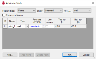
All feature object properties are edited using a single spreadsheet. This makes it possible to cut and paste feature object data using the clipboard and it makes it easier to edit entire columns of data at once. Filters at the top of the dialog control what type of objects are displayed. | All feature object properties are edited using a single spreadsheet. This makes it possible to cut and paste feature object data using the clipboard and it makes it easier to edit entire columns of data at once. Filters at the top of the dialog control what type of objects are displayed. | ||
The specific attributes available in this dialog vary depending on options selected in the ''Coverage Setup'' dialog. | |||
[[File:FeatureAttributes.png|thumb|none|400 px|Example of the feature object ''Attribute Table'']] | |||
== Map To Submenu == | == Map To Submenu == | ||
Coverages can be mapped to other geometric objects or | Coverages can be mapped to other geometric objects or numerical models by selecting the corresponding command from the ''Map to'' submenu. Options include: | ||
* [[GMS:Map_to_Modules#Map_.E2.86.92_TIN|'''Map to TIN''']] [[File:Map to TIN Macro.svg|16 px]] – Creates a TIN using each polygon in the coverage. | |||
* [[GMS:Map_to_Modules#Map_to_2D_Mesh|'''Map to 2D Mesh''']] [[File:Map to 2D Mesh Macro.svg|16 px]] – Creates a 2D Mesh on the interior of all of the polygons in the current coverage. | |||
* [[GMS:Map_to_Modules#Map_to_3D_Grid|'''Map to 3D Grid''']] [[File:Map to 3D Grid Macro.svg|16 px]] – Opens the ''Create Grid'' dialog. | |||
* [[GMS:Creating_and_Editing_UGrids#Map_.E2.86.92_UGrid|'''Map to UGrid''']] [[File:Map to UGrid Macro.svg|16 px]] – Creates a UGrid from feature objects. | |||
* [[GMS:Map_to_Modules#Map_to_2D_Scatter_Points|'''Map to 2D Scatter''']] [[File:Map to 2D Scatter Macro.svg|16 px]] – Creates a scatter point set from the points and nodes and vertices of the current coverage. | |||
* [[GMS:Map to MODFLOW|'''Map to MODFLOW''']] [[File:Map to MODFLOW Macro.svg|16 px]] – Converts a conceptual model to a MODFLOW numerical model. | |||
* [[GMS:Map_to_Models#Map_to_FEMWATER|'''Map to FEMWATER''']] [[File:Map to FEMWATER Macro.svg|16 px]] – Converts a conceptual model to a FEMWATER numerical model. | |||
* [[GMS:Map_to_Models#Map_to_MT3DMS|'''Map to MT3DMS''']] [[File:Map to MT3DMS Macro.svg|16 px]] – Converts a conceptual model to a MT3DMS numerical model. | |||
* '''Map to SEEP2D''' [[File:Map to SEEP2D Macro.svg|16 px]] – Converts a conceptual model to a SEEP2D numerical model. | |||
== Merge Coverage == | |||
Multiple coverages can be merged in a new coverage. Do this by selecting two or more coverages using the ''Shift'' key, then right-click on the coverages and select the '''Merge''' command. A new coverage will be created in the Project Explorer. This merged coverage will contain all properties and feature objects that existed on each coverage used to create the merged coverage. | |||
==Coverage Properties== | |||
Right-click on a coverage and selecting the ''Properties'' command will open a ''Properties'' dialog. This dialog will contain information about the coverage, such as the number of feature objects and projection. The dialog also contains a ''Notes'' tab for saving comments or other notes about the coverage. | |||
== | ==See also== | ||
[[GMS:Conceptual | *[[GMS:Conceptual Model|Conceptual Model]] | ||
*[[GMS:Feature Objects|Feature Objects]] | |||
{{Navbox GMS}} | {{Navbox GMS}} | ||
[[Category:Project Explorer]] | |||
[[Category:Map Module]] | |||
[[Category:Feature Objects]] | |||
[[Category:GMS Map Dialogs]] | |||


