WMS:Flow Paths and Barrier Coverages
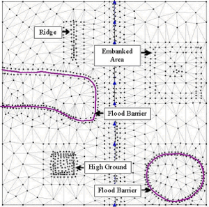
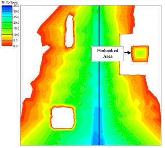
Figure (a) shows natural high ground and embankment in a TIN and the location of water levels and flood barriers used in the floodplain delineation. This and the subsequent figures demonstrate the following options: 1) floodplain delineation without considering the flow path option, 2) floodplain delineation considering the flow path option, and 3) floodplain delineation considering flood barriers.
The flow path option in the floodplain delineation process ensures that the sources of water (i.e. the water levels) and the areas flooded are hydraulically connected. This is an important option because if not applied, the process may interpolate water levels while ignoring obstructions between the water levels and the point of interpolation. The effect of such interpolation is shown in Figure (b) where the floodplain is delineated without considering flow paths. The figure shows two flooded areas separated from each other by a natural embankment. Considering the water levels, which are located outside the embankment and lower than the elevation of the embankment, the area inside the embankment should not be flooded. Therefore, it is obvious that the flooding inside the embankment is the effect of the interpolation done by the process without checking hydraulic connectivity.
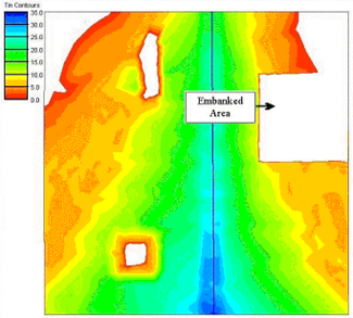
The more realistic flooding scenario is simulated when flow paths are considered as shown in Figure (c). In this case the process first checks for hydraulic connectivity before performing any interpolation at any location inside the embankment. Since the water is obstructed by the embankment the process does not find any flow paths. As a result the area inside the embankment remains flood free.
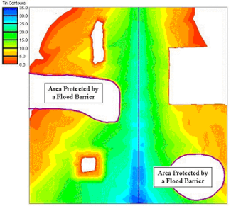
Not all natural and artificial flood obstructions are well represented by digital terrain models. The effect of these obstructions cannot be simulated with the flow path option alone. The use of flood barrier coverages along with the flow path option provides a way to address this issue in the floodplain delineation process. The effect of using flood barriers in the floodplain delineation is demonstrated in Figure (d), which shows an area on each side of the river that is protected by a floodwall. Since the elevations in the TIN do not show the presence of the floodwalls, a flood barrier coverage is used to simulate the effect in the floodplain delineation. While checking hydraulic connectivity, the process recognizes those barriers and therefore, reports the areas inside the barrier as flood free.
Related Topics
WMS – Watershed Modeling System | ||
|---|---|---|
| Modules: | Terrain Data • Drainage • Map • Hydrologic Modeling • River • GIS • 2D Grid • 2D Scatter |  |
| Models: | CE-QUAL-W2 • GSSHA • HEC-1 • HEC-HMS • HEC-RAS • HSPF • MODRAT • NSS • OC Hydrograph • OC Rational • Rational • River Tools • Storm Drain • SMPDBK • SWMM • TR-20 • TR-55 | |
| Toolbars: | Modules • Macros • Units • Digitize • Static Tools • Dynamic Tools • Drawing • Get Data Tools | |
| Aquaveo | ||


