WMS:HY-12
| This contains information about features no longer supported for the current release of WMS. The content may not apply to current versions. Technical support and bugfixes are not provided for this feature. |
The US Federal Highway Administration's HY-12 is a DOS-based storm drain analysis program that can be used for designing inlets, pipes, and the general layout of a storm drain network. An HY-12 model can be generated by drawing the proposed pipe and inlet locations in a storm drain coverage. Then the map module locations are converted to a 1D schematic where the HY-12 model parameters are defined. Many of the HY-12 computations, such as channel calculations, curb and gutter calculations, and rational method computations, are based on computations in FHWA's Hydraulic Toolbox software. Refer to both the Hydraulic Toolbox and the HY-12 documentation to learn about the specific computation methods used in HY-12.
The HY-12 model is included with all paid editions of WMS. WMS 10.1 and later versions include the ability to run a simple HY-12 model (fewer than 50 nodes) without a license of WMS.
Last updated: 2022
HY-12 Menu
The HY-12 menu has the following commands:
- Import HY-12 File
- Export HY-12 Export
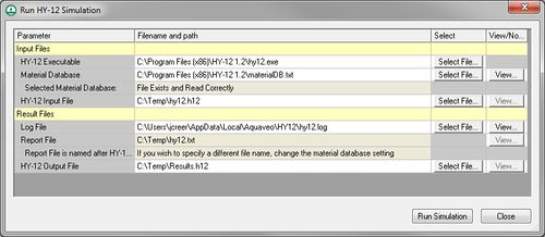
- Run HY-12 – Opens the Run HY-12 Simulation dialog.
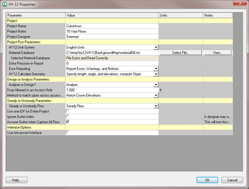
- Edit Project Parameters – Opens an HY-12 Properties dialog where parameters for the project can be specified.
- Edit Parameters – Opens an HY-12 Properties dialog where parameters for nodes and links can be specified.
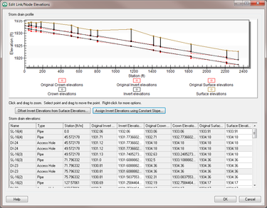
- Edit Elevations – Opens an Edit Link/Node Elevations dialog that allows editing link and node elevations between selected links and/or nodes.
- View Detailed Link/Node Output – Creates a text file describing the detailed link and node computation results.
- View Hydrographic Plots – Shows hydrograph plots for the selected link and/or node (Unsteady flow simulations only).
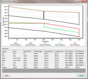
- View EGL and HGL Plots – Brings up the EGL and HGL Profiles dialog.
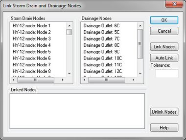
- Link Outlets and Inlets – Brings up the Link Storm Drain and Drainage Nodes dialog.
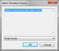
- Assign Elevations – This group of commands will assign elevation data from a TIN to each node and link. Each command brings up a corresponding Select Elevation Source dialog where the elevation source data can be selected.
- To Ground
- To Access Hole
- To Inlets
- To Outlets
- To Channels
- To Gutters
- To Pipes
- To Pipe Storage
- Assign Lengths and Orientations
- Assign Hydrology Data
- Area – This command assigns the computed basin areas upstream from the outlet points when having linked to the rational method computations at each node.
- Runoff Coefficient – This command areaweights the runoff coefficients for the sub-basins assigned to each outlet and assigns the area-weighted runoff coefficient to the rational method computations at each node.
- Time of Concentration – This command computes the average time of concentration for the sub-basins assigned to each outlet and assigns this time of concentration to the rational method computations at each node.
HY-12 Parameters
The HY-12 Model has several HY-12 Properties dialog where parameters can be defined.
HY-12 Project Properties
The HY-12 Properties is reached by using the Edit Project Parameters command in the HY-12 menu.
HY-12 Node and Link Properties
Select either a node or a link using the Select Hydraulic Node tool or the Select Hydraulic Link tool then right-click. In the right-click menu select the Edit Parameters command. This will bring up the HY-12 Properties dialog for Nodes and Links. This dialog can also be reached by using the Edit Parameters command in the HY-12 dialog.
There are two versions of the HY-12 link/node properties dialog. The simplified interface provides an intuitive way to edit link and node information and many projects will only require using this interface. A person can add pipes or channels to links in the simplified interface. A person can also add Rational method calculations, inlets, access holes, or outfalls to nodes in the simplified interface. Using the simplified interface, it's not necessary to define advanced attributes that are not normally needed in an HY-12 storm drain simulation. A useful feature in the simplified link/node properties dialog is the ability to sort data based on any of the attributes. For example, if wanting to find any pipes with negative slopes, it's possible to sort links based on slope and any link with a negative slope would show up at the top of the list.
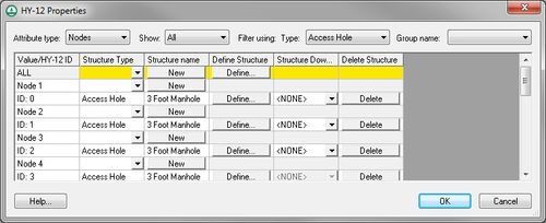
If needing to define structures that are not supported in the simplified interface or if needing to define advanced structure parameters, turn on the Use Advanced Interface option in the HY-12 Project Parameters dialog and edit the project parameters using the advanced interface.
Information on tems in the Advanced interface dialog
- Attribute Type' – Chooses between viewing nodes or links.
- Show – Searches between all or selected nodes or links.
- Filter using: Type – Views nodes or links based on the structure type.
- Group Name – Not used
- Value/HY-12 ID – Shows the node or link value and the corresponding HY-12 ID.
- Structure Type – Assigns the structure type for the node or link. Selecting the New button will assign the structure type. The following structure types are available:
Node Structure Link Structure Access Hole Channel Gutter Inlet Gutter Junction Pipe Minor Loss Pipe Storage Outfall Pump Station Rational Method Basin Reservoir Transition
- Structure Name
- New – Clicking on this button will assign the structure type to the selected nodes or links.
- Define Structure
- Define – Selecting this button will bring up a HY-12 Properties dialog where definitions for the structure type can be entered.
- Structure Downstream' – Shows structures assigned as downstream structures.
- Delete Structure
- Delete – Removes the assigned structure type.
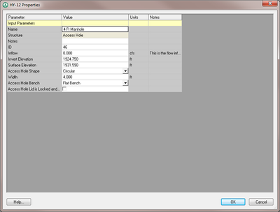
Once parameters have been assigned for nodes and links, double-clicking on a node or link will bring up a HY-12 Properties dialog showing the attributes for that node or link.
Edit Elevations
The HY-12 Edit Elevations menu item is a useful tool for editing elevation profiles between selected links or nodes. To edit elevations between two links or nodes, select the upstream and the downstream points for editing elevations and then select HY-12 | Edit Elevations. The Edit Link/Node Elevations dialog will appear. In this dialog, modify elevation values graphically from the plot window or edit individual elevation values in the spreadsheet below the plot.
There are two buttons that may be useful for defining elevations in the storm drain network.
- Offset Invert Elevations from Surface Elevations – Allows offsetting pipes from the ground surface using either a given cover depth or a given invert depth. A prompt will appear asking which of these options to use as well as the distance of the crown or invert below the ground after clicking on the button.
- Assign Invert Elevations using Constant Slope – Assigns pipe and node elevations to the storm drain profile based on a starting elevation as well as a slope. By default, the starting elevation is the invert elevation of the most upstream selected point and the slope is the average slope of the storm drain network. A prompt will appear for these two values after pressing the button.
HGL and EGL Profiles
Hydraulic Grade Line (HGL) and Energy Grade Line (EGL) profile plots can be created after running the HY-12 model, selecting two links or nodes, and then by using the View HGL and EGL Plots command in the HY-12 menu.
Link Storm Drain and Drainage Nodes
The option to link storm drain and drainage coverage nodes is a useful feature if wanting to use the rational method data from the hydrologic model as an input to the HY-12 model. After defining the rational method information, use this menu item to link rational method information at the outlets in the hydrologic model to inlets in the HY-12 model.
- Storm Drain Nodes
- Drainage Nodes
- Linked Nodes
- Link Nodes
- Auto Link
- Tolerance
- Unlink Nodes
Run HY-12
The Run HY-12 command will bring up the Run HY-12 Simulation dialog where specifications can be reviewed. Clicking OK on this dialog will run the model. HY-12 simulations with more that 50 nodes cannot be run unless there is a license to WMS.
Related Topics
WMS – Watershed Modeling System | ||
|---|---|---|
| Modules: | Terrain Data • Drainage • Map • Hydrologic Modeling • River • GIS • 2D Grid • 2D Scatter |  |
| Models: | CE-QUAL-W2 • GSSHA • HEC-1 • HEC-HMS • HEC-RAS • HSPF • MODRAT • NSS • OC Hydrograph • OC Rational • Rational • River Tools • Storm Drain • SMPDBK • SWMM • TR-20 • TR-55 | |
| Toolbars: | Modules • Macros • Units • Digitize • Static Tools • Dynamic Tools • Drawing • Get Data Tools | |
| Aquaveo | ||
