WMS:TIN Menu
From XMS Wiki
(Redirected from WMS:TIN Menus)
Jump to navigationJump to search
The TIN menu in the Terrain Data module has the following commands:
- TIN Options
- Brings up the TIN Options dialog. See the article TIN Options for more information.
- Merge
- It is possible to merge a selected TIN with another TIN using the Merge command in the TIN menu. This is particularly useful if wanting to merge a TIN generated from one program with a TIN derived from a background elevation source such as a DEM. For example, a project may have surveyed data with a lot of detail for a part of the project (such as a roadway profile) and it is desired to combine that with a TIN derived from a DEM of the surrounding area.
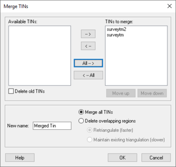
- The following dialog is used to select existing TINs for merging. The merged TINs can be completed merged (all vertices combined and retriangulated), or specified to have vertices in overlapping regions deleted. The old TINs can be kept or deleted.
- The following rules are adhered to when merging a list of TINs:
- The TIN at the bottom of the list of TINs to merge has the highest priority, meaning that all of its triangle edges will be preserved while vertices that overlap from TINs higher in the list will be deleted.
- If a region being deleted from one TIN overlaps any stream vertices on the TIN being deleted, the stream will be split. The stream will be cut off wherever it "enters" the TIN selected for merging and begin again upstream where it "exits."
- Drainage data will be lost and not transferred as part of the merged TIN.
- Fill
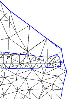
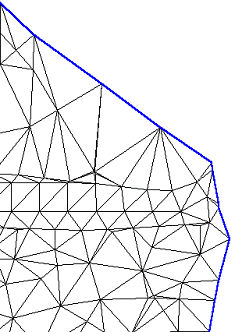
- The Fill command triangulates a selected polygon and merges it with the original TIN. Vertices should be distributed according to the density of TIN vertices desired on the interior of the TIN. The primary purpose is to fill in an area where data is missing on a TIN, or where to retriangulate to a higher density.
- It's necessary to have some kind of background elevation behind the polygon (e.g. a DEM or another TIN), or the resulting vertices within the polygon will all have zero elevations.
- Filter
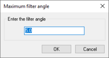
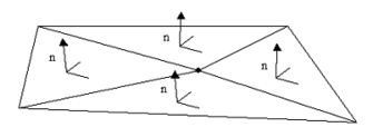
- Redundant and overlapping data may exist in a scattered XYZ datasets. WMS offers the ability to filter the data and remove unnecessary data points in relatively flat areas in the Filter command from the TIN menu. This brings up the Maximum Filter Angle dialog where an angle is specified. Each data point is checked to see if it is in a flat region by dotting the normals of the surrounding triangles.
- If the normals are all within the specified angle, the region is considered flat and the point is deleted.
- This type of processing is very important when trying to use LIDAR data. Typical LIDAR collection results in resolutions of 1–3 meters so that good detail of flood plains and channel banks is achieved. However, this leaves massive amounts of points in relatively flat areas where the increased resolution is not required (it would be like asking a surveyor to get points every 5 feet just so he doesn't miss anything when hopefully he can be much smarter). The filtering eliminates the points where they are not needed and retains the important points. (The reference to Creighton Omer's paper is about a study using this technique on LIDAR data for hydraulic modeling that concludes a filter angle of 4-8 degrees can be used that will result in up to 85% data reduction without impacting hydraulic modeling results.)
- Trim
- Trimming allows eliminating all vertices that are outside of a selected feature polygon. First, create the feature polygon in the Map module, then select the polygon to use prior to selecting the Trim command from the TIN menu (Terrain Data module).
Data
- The TIN menu offers four options for the using data under the Data submenu:
- Calculator
- Brings up the Data Calculator. See Datasets for more information.
- Smooth Dataset
- See Smooth Dataset for more information.
- Map Elevation
- See the Mapping Elevations section of the Datasets article.
- Film Loop
- See Setting up Film Loops for more information.
Vertices
- See Vertices for more information.. The Tin menu has following options for vertices under the Vertices submenu:
- Transform
- Used to move TIN vertices according to a specified transformation.
- Lock/Unlock
- Selected vertices can be locked to prevent them from being dragged or edited.
- Delete Duplication
- Removes vertices that duplicate the same xy location as another vertex.
- Smooth Pits
- Adjusts the elevations of pits in order to remove them.
Triangles
- See the article Triangulation for more information. The TIN menu gives the following options for triangles under the Triangles submenu:
- Triangulate
- Triangulates the vertices of the TIN.
- Insert Breakline
- Optimize Triangulation
- Optimizes triangulation according to criteria specified in the TIN Options dialog.
- Check Long/Thin Triangles
- Remove Flat Triangles
- Attempts to eliminate flat triangles on a TIN.
Interpolation
- Interpolate TIN To TIN
- The Interpolate to TIN command of the TIN menu allows interpolating the elevations of the active TIN to one or more TINs. If more than one other TIN exists, a dialog will appear that allows selecting the TIN(s) to interpolate to. No changes occur in the elevations of the active TIN.
- Interpolate TIN To 2D Grid
- The Interpolate to 2D Grid command of the TIN menu interpolates the elevations of the active TIN to the 2D grid. Only available if both a TIN and a 2D grid exist.
- Interpolate TIN to Feature Objects
- This command will interpolate the elevations to feature objects in the active coverage inside the Map module.
Convert
- See Convert TINs for more information. The following conversion options are available for TINs:
- TIN Contours → Feature
- Converts the current linear contours from the TIN to a series of feature arcs which could then be exported as a shapefile.
- TIN Boundary → Feature
- Creates a boundary feature polygon from the vertices on the boundary of the TIN.
- TIN → Scatter Points
- Creates a 2D scatter point set from the TIN.
- TIN → DEM
- Creates a DEM from the TIN.
Related Topics
WMS – Watershed Modeling System | ||
|---|---|---|
| Modules: | Terrain Data • Drainage • Map • Hydrologic Modeling • River • GIS • 2D Grid • 2D Scatter |  |
| Models: | CE-QUAL-W2 • GSSHA • HEC-1 • HEC-HMS • HEC-RAS • HSPF • MODRAT • NSS • OC Hydrograph • OC Rational • Rational • River Tools • Storm Drain • SMPDBK • SWMM • TR-20 • TR-55 | |
| Toolbars: | Modules • Macros • Units • Digitize • Static Tools • Dynamic Tools • Drawing • Get Data Tools | |
| Aquaveo | ||
