WMS:DEM Basins: Difference between revisions
No edit summary |
|||
| (3 intermediate revisions by one other user not shown) | |||
| Line 2: | Line 2: | ||
==Defining Basins== | ==Defining Basins== | ||
Each time a feature outlet point is created, a basin for each upstream feature arc is created for the hydrologic modeling tree. This means that the stream arcs themselves are associated with a basin even before the '''Define Basins''' command is issued. When the command is used the DEM points intersected by the stream arcs are assigned the basin ID already given to the arcs. The Define Basins procedure then continues by tracing the flow paths of the remaining DEM points until a point | Each time a feature outlet point is created, a basin for each upstream feature arc is created for the hydrologic modeling tree. This means that the stream arcs themselves are associated with a basin even before the '''Define Basins''' command is issued. When the command is used the DEM points intersected by the stream arcs are assigned the basin ID already given to the arcs. The Define Basins procedure then continues by tracing the flow paths of the remaining DEM points until a point that has already been assigned a basin ID is intersected. The result is that each DEM point gets assigned the ID of the sub-basin it belongs to. | ||
Knowing that DEM flow paths only run until a stream is intersected can help | Knowing that DEM flow paths only run until a stream is intersected can help modify the results of a delineation by creating user-defined stream arcs (independent of those created using the '''DEM→Stream Arcs''' command) that "intercept" flow along a line that might not be represented by the underlying elevations. An example of this is along a highway embankment. The scale of most DEMs does not capture a feature such as a highway embankment, yet it is an important feature in basin delineation. It is possible to create a stream arc along the highway alignment and leading to a culvert or bridge crossing. The resulting basin delineation will then "capture" all flow that intersects the line and account for the raised highway embankment. The following figures illustrate the use of this concept. | ||
<gallery widths="400 px" heights="200 px"> | <gallery widths="400 px" heights="200 px"> | ||
| Line 13: | Line 13: | ||
</gallery> | </gallery> | ||
Additional outlet points can be created by changing the attribute of existing arc nodes to outlets or by converting arc vertices to nodes and then changing the attribute to outlet. The [[WMS:Drainage_Module_Menus|'''Node↔Outlet''']] command can be used to accomplish this. Any selected node or vertex will automatically be converted to an outlet node when using this command. Any selected outlet node will automatically be converted to a generic node type when using this command. | Additional outlet points can be created by changing the attribute of existing arc nodes to outlets or by converting arc vertices to nodes and then changing the attribute to the outlet. The [[WMS:Drainage_Module_Menus|'''Node↔Outlet''']] command can be used to accomplish this. Any selected node or vertex will automatically be converted to an outlet node when using this command. Any selected outlet node will automatically be converted to a generic node type when using this command. | ||
The '''Define Basins''' command can be used any number of times to redefine basins after the addition/deletion of outlet nodes. | The '''Define Basins''' command can be used any number of times to redefine basins after the addition/deletion of outlet nodes. | ||
| Line 36: | Line 36: | ||
==Editing Basin Variables== | ==Editing Basin Variables== | ||
The '''Basin Variables''' button will let | The '''Basin Variables''' button will let you view or edit any of the [[WMS:Variables Computed by WMS|basin variables that are computed by WMS]]. While it is unnecessary to edit these variables, in some cases it may be desired to override what WMS has computed and use a value derived through a separate analysis. | ||
==Merge Selected Basins== | ==Merge Selected Basins== | ||
The '''Merge Selected Basins''' command merges two selected sub basins into a single basin. The two sub basins must be directly connected to the same outlet point. | The '''Merge Selected Basins''' command merges two selected sub-basins into a single basin. The two sub-basins must be directly connected to the same outlet point. | ||
By default WMS will create a separate basin for each upstream branch of an outlet point. However, some may wish to combine basins of all branches of an outlet into a single basin. The '''Merge Selected Basins''' command allows doing this. | By default, WMS will create a separate basin for each upstream branch of an outlet point. However, some may wish to combine basins of all branches of an outlet into a single basin. The '''Merge Selected Basins''' command allows doing this. | ||
An alternative approach (and really a better way to do it for data management purposes) is to define the basin just downstream of the junction as illustrated in the following figure. | An alternative approach (and really a better way to do it for data management purposes) is to define the basin just downstream of the junction as illustrated in the following figure. | ||
| Line 56: | Line 56: | ||
==Delineate Basins Wizard== | ==Delineate Basins Wizard== | ||
The [[WMS:DEM Guidelines|DEM Guidelines]] | The [[WMS:DEM Guidelines|DEM Guidelines]] article outlines as steps the basic process for watershed characterization with DEMs. Some of these steps are repeated quite frequently. Rather than needing to perform them one at a time, select the '''Delineate Basins Wizard''' command and the steps will be performed in succession. | ||
In order to run the | In order to run the ''Delineate Basin Wizard'', the project should have already read in elevations (edited if desired), run TOPAZ to compute the flow directions and flow accumulations, and established initial outlet points. The wizard will then convert the outlets to streams, define basins, convert the basins to polygons, and compute basin data in succession. | ||
The delineation wizard is best suited for use when there is a single basin to delineate rather than several smaller basins that make up a larger basin. For such cases it is probably best to follow the individual steps to prevent lumping the multiple smaller sub-basins into a single large basin. | The delineation wizard is best suited for use when there is a single basin to delineate rather than several smaller basins that make up a larger basin. For such cases it is probably best to follow the individual steps to prevent lumping the multiple smaller sub-basins into a single large basin. | ||
| Line 72: | Line 72: | ||
* [[WMS:Importing Flow Directions and Accumulations|Importing Flow Directions and Accumulations]] | * [[WMS:Importing Flow Directions and Accumulations|Importing Flow Directions and Accumulations]] | ||
* [[WMS:Drainage Module Menus|Drainage Module Menus]] | * [[WMS:Drainage Module Menus|Drainage Module Menus]] | ||
* [[WMS: | * [[WMS:Drainage_Module_Menus#Drainage_DEM_Menu|DEM → Stream Arcs]] | ||
| Line 79: | Line 79: | ||
[[Category:DEM|Basins]] | [[Category:DEM|Basins]] | ||
[[Category:WMS Basins|DEM]] | [[Category:WMS Basins|DEM]] | ||
[[Category:Gallery]] | |||
Latest revision as of 20:51, 20 May 2020
Defining Basins
Each time a feature outlet point is created, a basin for each upstream feature arc is created for the hydrologic modeling tree. This means that the stream arcs themselves are associated with a basin even before the Define Basins command is issued. When the command is used the DEM points intersected by the stream arcs are assigned the basin ID already given to the arcs. The Define Basins procedure then continues by tracing the flow paths of the remaining DEM points until a point that has already been assigned a basin ID is intersected. The result is that each DEM point gets assigned the ID of the sub-basin it belongs to.
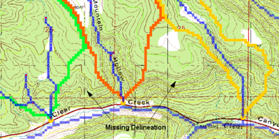
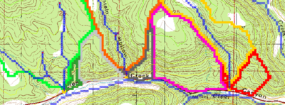
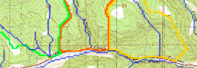
Knowing that DEM flow paths only run until a stream is intersected can help modify the results of a delineation by creating user-defined stream arcs (independent of those created using the DEM→Stream Arcs command) that "intercept" flow along a line that might not be represented by the underlying elevations. An example of this is along a highway embankment. The scale of most DEMs does not capture a feature such as a highway embankment, yet it is an important feature in basin delineation. It is possible to create a stream arc along the highway alignment and leading to a culvert or bridge crossing. The resulting basin delineation will then "capture" all flow that intersects the line and account for the raised highway embankment. The following figures illustrate the use of this concept.
Figure 3: If leaving the outlet of the basin at the bottom node, WMS will create separate basins for the main branch and each branch along the road. In order to combine them into a single basin a small (about one cell in length or less) stub stream is created so that only a single drainage will be used. Remember that WMS will create a separate basin for each upstream branch from an outlet point.
Additional outlet points can be created by changing the attribute of existing arc nodes to outlets or by converting arc vertices to nodes and then changing the attribute to the outlet. The Node↔Outlet command can be used to accomplish this. Any selected node or vertex will automatically be converted to an outlet node when using this command. Any selected outlet node will automatically be converted to a generic node type when using this command.
The Define Basins command can be used any number of times to redefine basins after the addition/deletion of outlet nodes.
Basin Boundaries to Polygons
Once the desired sub-basin delineation from the DEM points has been defined, the basin boundaries can be converted to feature polygons. This is done by tracing the boundaries between sub-basins to generate arcs. After all of the boundaries have been defined the arcs are converted to polygons and the polygons assigned the appropriate basin ID.
The resulting polygon boundaries will be jagged because the arcs created for the polygons trace around each raster DEM cell. In order to make the boundaries appear smoother and more visually appealing, redistribute vertices along a cubic spline. If using a 30 meter resolution DEM then the average length between vertices will be approximately 30 meters and it is suggested to redistribute to about 100 meters spacing (be sure to turn on the cubic spline option). In general, redistributing to about three times the DEM resolution will produce good results.
Compute Basin Data
When the drainage coverage feature objects are used to create a hydrologic model the area of the polygons can be determined and used in any of the supported hydrologic models. If the points/vertices used to create the feature arcs also have z values associated with them then WMS will make a rough estimate of the longest flow path and slope along such a path. Finally, if a watershed has been derived from feature objects, and also has a background DEM, compute most of the basin data parameters using the following steps:
- Import/read the DEM.
- Compute the flow directions using TOPAZ.
- Use the Polygon Basin IDs→DEM command found in the DEM menu in the Drainage module to assign DEM cells a basin id from the feature object polygons.
- Choose the Compute Basin Data command from the Feature Objects menu of the Map module.
Of course, the results will only be approximate since the actual basin boundaries will not have been derived from the computed flow direction data, but it will provide a reasonable estimate. Ideally, derive the basin boundaries from the DEM and flow direction data and then use the Compute Basin Data command in the DEM menu of the Drainage module.
Computing Basin Data
After defining basin boundaries, attributes such as basin areas, slopes, and stream lengths can be computed using the Compute Basin Data command. These attributes are all geometric parameters used in defining basins and routing networks in HEC-1, TR-20, and other hydrologic models. If the basins are changed in any way, the drainage data must be recomputed using this command. When computing basin data the model units and the parameter units must be specified. The only choices available for model units are feet and meters whereas the parameter for area include square miles, square kilometers, and acres, and for distance include mile, kilometer, feet, and meters. A complete definition of the different geometric attributes computed and how they may be used to compute travel times (lag time, time of concentration) is given in the Hydrologic/Hydraulic Calculations page.
Editing Basin Variables
The Basin Variables button will let you view or edit any of the basin variables that are computed by WMS. While it is unnecessary to edit these variables, in some cases it may be desired to override what WMS has computed and use a value derived through a separate analysis.
Merge Selected Basins
The Merge Selected Basins command merges two selected sub-basins into a single basin. The two sub-basins must be directly connected to the same outlet point.
By default, WMS will create a separate basin for each upstream branch of an outlet point. However, some may wish to combine basins of all branches of an outlet into a single basin. The Merge Selected Basins command allows doing this.
An alternative approach (and really a better way to do it for data management purposes) is to define the basin just downstream of the junction as illustrated in the following figure.
Delete NULL Basins Cell Data
The Delete Null Basins Cell Data command is used to delete all DEM points which are not currently assigned a basin ID. The DEM is reduced to a bounding rectangle of the watershed and elevation values within the rectangle but outside of the watershed are converted to NODATA.
Polygon Basin IDs to DEM
The Polygon Basin IDs→DEM command assigns basin IDs to the DEM from a set of polygons that represent basin boundaries. This command is useful if not delineated the basin using the flow directions and flow accumulations from within WMS, but instead using a set of polygons representing basin boundaries with unique IDs. Once basin IDs have been assigned, basin data such as area, average slope, etc. can be computed.
Only use this option if there is a set of feature objects already and/or wishing to “over-ride” the basin boundaries that are determined from elevation data. This might occur in an urban watershed where streets, canals, etc. may not be apparent in the digital elevation data.
Delineate Basins Wizard
The DEM Guidelines article outlines as steps the basic process for watershed characterization with DEMs. Some of these steps are repeated quite frequently. Rather than needing to perform them one at a time, select the Delineate Basins Wizard command and the steps will be performed in succession.
In order to run the Delineate Basin Wizard, the project should have already read in elevations (edited if desired), run TOPAZ to compute the flow directions and flow accumulations, and established initial outlet points. The wizard will then convert the outlets to streams, define basins, convert the basins to polygons, and compute basin data in succession.
The delineation wizard is best suited for use when there is a single basin to delineate rather than several smaller basins that make up a larger basin. For such cases it is probably best to follow the individual steps to prevent lumping the multiple smaller sub-basins into a single large basin.
Manually Edit Delineated Basin
Occasionally the DEM does not contain all elevation data so when delineating a basin, the resulting watershed is inaccurate. This could occur if there is a road or other man-made obstacle dividing the watershed in half. In cases like these, it is necessary to manually edit the watershed boundaries.
- NOTE: care should be taken when manually editing a watershed as this can lead to inaccurate results if not done correctly.
Upon delineating a basin, WMS creates a coverage that is usually called "Drainage". Select this coverage then use the Select Feature Vertex tool to drag out where the new border should be. Once the polygon is where it should be, switch to the Drainage module then select DEM | Polygon Basin IDs→DEM. This should redefine the basin where the polygon was.
Related Topics
- Watershed Delineation with DEMs
- Importing Flow Directions and Accumulations
- Drainage Module Menus
- DEM → Stream Arcs
WMS – Watershed Modeling System | ||
|---|---|---|
| Modules: | Terrain Data • Drainage • Map • Hydrologic Modeling • River • GIS • 2D Grid • 2D Scatter |  |
| Models: | CE-QUAL-W2 • GSSHA • HEC-1 • HEC-HMS • HEC-RAS • HSPF • MODRAT • NSS • OC Hydrograph • OC Rational • Rational • River Tools • Storm Drain • SMPDBK • SWMM • TR-20 • TR-55 | |
| Toolbars: | Modules • Macros • Units • Digitize • Static Tools • Dynamic Tools • Drawing • Get Data Tools | |
| Aquaveo | ||


