GMS:MODFLOW Display Options: Difference between revisions
From XMS Wiki
Jump to navigationJump to search
No edit summary |
No edit summary |
||
| Line 21: | Line 21: | ||
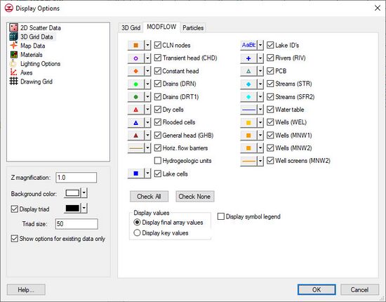
|PCB || Displays a symbol in the center of each cell that has a [[GMS:PCB Package|prescribed or constant concentration boundary]]. The symbol, the symbol size, and symbol color can be adjusted by clicking on the button to the left of the Lake cells checkbox. | |PCB || Displays a symbol in the center of each cell that has a [[GMS:PCB Package|prescribed or constant concentration boundary]]. The symbol, the symbol size, and symbol color can be adjusted by clicking on the button to the left of the Lake cells checkbox. | ||
|- | |- | ||
| Water table || When a grid cross section is displayed in orthogonal mode, this tool superimposes the water table defined by a MODFLOW solution on the layer geometry. The water table is defined as the head value in the uppermost active cell. If the water table display is on, all contours (head, concentration, etc.) are clipped so that they lie at or below the water table. This option is only available if the ''True Layer display'' option is active under the ''3D Grid'' display options tab. | | Water table || When a grid cross section is displayed in orthogonal mode, this tool superimposes the water table defined by a MODFLOW solution on the layer geometry. The water table is defined as the head value in the uppermost active cell. If the water table display is on, all contours (head, concentration, etc.) are clipped so that they lie at or below the water table. This option is only available if the [[GMS:3D Grid Viewing Modes#True_Layer_Mode|''True Layer display'']] option is active under the ''3D Grid'' display options tab. | ||
|- | |- | ||
| Check All ||Turns on all display options. | | Check All ||Turns on all display options. | ||
