GMS:SUB Package
| MODFLOW | |
|---|---|
| Pre-processing | |
| MODFLOW Commands | |
| Building a MODFLOW Model | |
| Map to MODFLOW | |
| Calibration | |
| Packages Supported in GMS | |
| Saving a MODFLOW Simulation | |
| Importing MODFLOW Files | |
| Unsupported MODFLOW Features | |
| Run MODFLOW | |
| Post-processing | |
| MODFLOW Display Options | |
| MODFLOW Post-Processing Viewing Options | |
| Reading a MODFLOW Simulation | |
| Tutorials | |
| Packages | |
| Flow: | BCF6, HUF, LPF, UPW |
| Solvers: | SMS |
| Other: | UZF1 |
The MODFLOW Subsidence (SUB) package simulates aquifer compaction and land subsidence. The SUB package includes the ability to simulate compaction in both elastic (recoverable) and inelastic (not recoverable) interbeds. It also includes the ability to simulate interbeds where drainage from the interbed is immediate (no-delay) or delayed. The MODFLOW SUB package can generate a binary vertical displacement file that is read by GMS and displayed as a dataset in the MODFLOW solution in the Project Explorer. A detailed description of the SUB input is available at the USGS website.
Contents
SUB Package Dialog
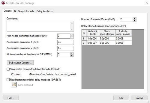
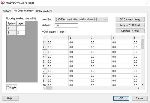
The SUB Package dialog provides an interface for adding and removing subsidence interbeds. The dialog is separated into three tabs. The Options tab includes general package options along with a table to edit delay interbed materials. The Non-Delay Interbed and Delay Interbed tabs allow adding interbeds and editing interbed array values.
Options Tab
The Options tab includes general SUB package options, options for saving and restarting Dstart and DHC values for delay interbeds, and material values for delay interbeds. The options are as follows:
- Comments – Place whatever comments are needed for the package.
- NN – Number of nodes used to discretize the half space to approximate the head distributions in systems of delay interbeds. Defaults to zero when there aren't any delay interbed layers specified.
- AC1 – Is an acceleration parameter. Used to predict the aquifer head at the interbed boundaries on the basis of the head change computed for the previous iteration. Values may range from 0.0 to 0.6.
- AC2 – Is an accleration parameter. It is a multiplier for the head changes to compute the head at a new iteration. Values may range from 1.0 to 2.0.
- ITMIN – The minimum number of iterations for which one-dimensional equations will be solved for flow in interbeds when the SIP package is used.
- SUB Output Options – Brings up a dialog where SUB package output options can be set. Values can either be printed to the model output file or saved as a binary file. The Save vert. disp. (Ifl8) option saves a binary file for vertical displacement that is included in the model solution as a dataset.
- NMZ – Sets the number of SUB package material values for the delay interbeds to be entered in the spreadsheet below. Defaults to zero when the number of delay interbeds (NDB) is zero (i.e. delay interbed layers have not been created).
- Vertical k – Vertical hydraulic conductivity for a delay interbed material.
- Elastic spec. storage – Elastic specific storage for a delay interbed material.
- Inelastic spec. storage – Inelastic specific storage for a delay interbed material.
No Delay and Delay Interbed Tabs
These two interbed tabs provide an interface for editing interbeds. In the spreadsheet to the left, interbeds can be added and removed. Also, the interbed's model layer can be set. The array spreadsheet to the right behaves similar to other areal spreadsheets. To edit a particular interbed array, select the row for the desired interbed in the spreadsheet at the left, and then select the desired array from the View/Edit combo box. The 2D Dataset → Array button can be used to set the viewed array values to a 2D dataset provided the 2D grid has the same number of rows and columns as the 3D grid. The Array → 2D Dataset button can be used to copy the viewed array to a 2D dataset; the same grid size limitations apply. The Constant → Array button can be used to set all of the values in the viewed array to the same value.
No Delay Interbed Arrays
- HC – Array specifying the preconsolidated head of the interbed. For a model with an initial steady state stress period, model cells in which specified preconsolidated head is above the steady state head, the HC value will be set to the steady state head. Has units of length.
- Sfe – Array specifying the elastic skeletal storage coefficient.
- Sfv – Array specifying the inelastic skeletal storage coefficient.
- COM – Array specifying the starting compaction. Has units of length.
Delay Interbed Arrays
- RNB – Array specifying the n-equiv of the interbed. This array is also used to define the areal extent of the interbed. For cells beyond the extent of the interbed enter a value less than 1.0.
- Dstart – Array specifying the starting head. Has units of length.
- DHC – Array specifying the preconsolidated head. For a model with an initial steady state stress period, model cells in which specified preconsolidated head is above the steady state head, the HC value will be set to the steady state head. Has units of length.
- DCOM – Array specifying the starting compaction. Has units of length.
- DZ – Array specifying the equivalent thickness of the interbed.
- NZ – Array specifying material zone numbers.
External Links
MODFLOW-2000 User Guide to the SUB Package
| [hide]GMS – Groundwater Modeling System | ||
|---|---|---|
| Modules: | 2D Grid • 2D Mesh • 2D Scatter Point • 3D Grid • 3D Mesh • 3D Scatter Point • Boreholes • GIS • Map • Solid • TINs • UGrids | |
| Models: | FEFLOW • FEMWATER • HydroGeoSphere • MODAEM • MODFLOW • MODPATH • mod-PATH3DU • MT3DMS • MT3D-USGS • PEST • PHT3D • RT3D • SEAM3D • SEAWAT • SEEP2D • T-PROGS • ZONEBUDGET | |
| Aquaveo | ||

