|
|
| Line 5: |
Line 5: |
|
| |
|
| ===MODFLOW=== | | ===MODFLOW=== |
| Several input arrays defining parameters such as starting head, [[GMS:IBOUND|IBOUND]], hydraulic conductivity, and transmissivity are defined in the [[GMS:Global Options/Basic Package|Global/Basic]] and [[GMS:BCF Package|BCF]], [[GMS:LPF Package|LPF]], or [[GMS:HUF Package|HUF]] packages. These arrays can be edited in the Basic and BCF/LPF/HUF Package dialogs, or they can be initialized using a [[GMS:MODFLOW Conceptual Model Approach|conceptual model]] in the [[GMS:Map Module|Map module]]. In many cases however, it is necessary to view or edit the values on a cell-by-cell basis. This can be accomplished using the '''Cell Properties''' command in the ''MODFLOW'' menu. | | Several input arrays defining parameters such as starting head, [[GMS:IBOUND|IBOUND]], hydraulic conductivity, and transmissivity are defined in the [[GMS:Global Options/Basic Package|Global/Basic]] and [[GMS:BCF Package|BCF]], [[GMS:LPF Package|LPF]], or [[GMS:HUF Package|HUF]] packages. These arrays can be edited in the ''Basic'' and ''BCF/LPF/HUF Package'' dialogs, or they can be initialized using a [[GMS:MODFLOW Conceptual Model Approach|conceptual model]] in the [[GMS:Map Module|Map module]]. In many cases however, it is necessary to view or edit the values on a cell-by-cell basis. This can be accomplished using the '''Cell Properties''' command in the ''MODFLOW'' menu. |
|
| |
|
| Before selecting the '''Cell Properties''' command, a set of cells should be selected using the cell selection tools. Once the command is selected, the [[GMS:MODFLOW|''MODFLOW'']] ''Cell Attributes'' dialog appears. | | Before selecting the '''Cell Properties''' command, a set of cells should be selected using the cell selection tools. Once the command is selected, the [[GMS:MODFLOW|''MODFLOW'']] ''Cell Attributes'' dialog appears. |
| MODFLOW |
|---|
| Pre-processing |
|---|
|
MODFLOW Commands |
|
Building a MODFLOW Model |
|
Map to MODFLOW |
|
Calibration |
|
Packages Supported in GMS |
|
Saving a MODFLOW Simulation |
|
Importing MODFLOW Files |
|
Unsupported MODFLOW Features |
|
Run MODFLOW |
| Post-processing |
|---|
|
MODFLOW Display Options |
|
MODFLOW Post-Processing Viewing Options |
|
Reading a MODFLOW Simulation |
| Tutorials |
|---|
| Packages |
|---|
| Flow: |
BCF6, HUF, LPF, UPW |
|---|
| Solvers: |
DE4, GMG, NWT, PCG,
PCGN, LMG, SIP, SOR,
SMS |
|---|
| Other: |
BAS6, BFH, CHD1, CLN,
DRN1, DRT1, EVT1, ETS1,
GAGE, GHB1, GNC, HFB1,
HUF, LAK3, MNW1, MNW2,
OUT1, RCH1, RIV1, SFR2,
STR1, SUB1, SWI2, WEL1,
UZF1 |
|---|
|
The Cell Properties dialog allows the user to edit cell properties. Most cell properties are associated with a model such as MODFLOW or MT3D. If no models exist in the GMS project then the Cell Properties dialog will only allow editing of the material assigned to the grid cell.
MODFLOW
Several input arrays defining parameters such as starting head, IBOUND, hydraulic conductivity, and transmissivity are defined in the Global/Basic and BCF, LPF, or HUF packages. These arrays can be edited in the Basic and BCF/LPF/HUF Package dialogs, or they can be initialized using a conceptual model in the Map module. In many cases however, it is necessary to view or edit the values on a cell-by-cell basis. This can be accomplished using the Cell Properties command in the MODFLOW menu.
Before selecting the Cell Properties command, a set of cells should be selected using the cell selection tools. Once the command is selected, the MODFLOW Cell Attributes dialog appears.
The parameters for the selected cells are changed by typing in new values in the edit fields. If more than one cell is selected when the Cell Properties command is selected, the available edit fields will be left blank (unless all values are the same for that parameter). To edit one of the parameters, click on the desired text edit field, enter the new value and click on the OK button. When the OK button is selected, only the parameters whose edit fields that have data are changed. This makes it possible to change one of the available parameters (e.g., transmissivity) for all of the selected cells while leaving the other parameters unchanged.
NOTE: When you are using materials to define the MODFLOW model, the Cell Properties dialog will show the material properties relating to the material of the selected cell. You will not be able to edit these values on a cell-by-cell basis, but you can either edit the material type for this cell if the active material set is the default material set, or you can change the material properties for the material (which affects every cell that uses that material).
MT3DMS/RT3D/SEAM3D
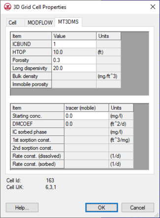
MT3D inputs that vary on a cell by cell basis can also be editing using this dialog and editing the data in the MT3D tab.

3D Grid Cell Properties dialog showing the
MODFLOW tab.
