GMS:CLN Process: Difference between revisions
From XMS Wiki
Jump to navigationJump to search
| (3 intermediate revisions by one other user not shown) | |||
| Line 38: | Line 38: | ||
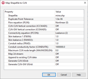
[[File:MapShapefileToCLN.png|thumb|280 px|The ''Map Shapefile to CLN'' dialog]] | [[File:MapShapefileToCLN.png|thumb|280 px|The ''Map Shapefile to CLN'' dialog]] | ||
===Map Shapefile to CLN=== | ===Map Shapefile to CLN=== | ||
The Connected Linear Network (CLN) process was developed for MODFLOW-USG to have the ability to model complex one-dimensional connected features that are much smaller than a groundwater flow model’s cells. A three-dimensional arc shapefile can be used to store the geometry and attributes of such a linear network. | The Connected Linear Network (CLN) process was developed for MODFLOW-USG to have the ability to model complex one-dimensional connected features that are much smaller than a groundwater flow model’s cells. A three-dimensional arc shapefile can be used to store the geometry and attributes of such a linear network. Attributes can optionally be applied to the arcs of the shapefile. | ||
Clicking the '''Map Shapefile to CLN''' button in the ''CLN Process'' dialog will first bring up a ''Select Arc Shapefile'' dialog. Once a shapefile has been selected, the ''Map Shapefile to CLN'' dialog will appear. The settings items in this dialog are used when attributes are not specified as arc attributes by the shapefile. | {| class="wikitable" | ||
|+'''Optional Shapefile Arc Attributes''' | |||
!width="100" align="left"|Name | |||
!width="250" align="left"|Description | |||
!width="110" align="left"|Default Value | |||
|- | |||
|IFLIN||Flow equation||Nonlinear (0) | |||
|- | |||
|ICCWADI||CLN to CLN Vertical correction||Off (0) | |||
|- | |||
|ICGWADI||CLN to GW Vertical correction||Off (0) | |||
|- | |||
|IFCON||Connectivity equation||Leakance (2) | |||
|- | |||
|FSKIN||Skin leakance 1||1.0 | |||
|- | |||
|FANISO||Skin leakance 2||1.0 | |||
|- | |||
|FRAD||Conduit radius||1.0 | |||
|- | |||
|CONDUITK||Conduit conductivity factor||1000000.0 | |||
|- | |||
|IBOUND|| ||1 | |||
|- | |||
|MAXNODELEN||Maximum CLN node length||0.0 | |||
|- | |||
|} | |||
Clicking the '''Map Shapefile to CLN''' button in the ''CLN Process'' dialog will first bring up a ''Select Arc Shapefile'' dialog. Once a shapefile has been selected, the ''Map Shapefile to CLN'' dialog will appear. The settings items in this dialog are used when attributes are not specified as arc attributes by the shapefile. The settings dialog includes some additional items. Arc points within the ''Duplicate Point Tolerance'' are snapped together and their CLN nodes are connected. By default, mapping a shapefile to CLN deletes the existing CLN data. When ''Append to existing CLN data'' is turned on the generated CLN data is appended to the existing data which can be useful when using CLN wells. With the final two settings, ''Generate CLN UGrid'' and ''Generate CLN-GW UGrid'', UGrids are generated which can be visualized in GMS for the generated CLN network and also the part of the CLN network that is connected to the groundwater model. | |||
==CLN Wells Dialog== | ==CLN Wells Dialog== | ||


