GMS:MNW2 Package: Difference between revisions
No edit summary |
|||
| Line 28: | Line 28: | ||
==Conceptual Model== | ==Conceptual Model== | ||
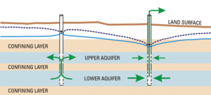
An MNW2 well can be added to a [[GMS:MODFLOW Conceptual Model Approach|conceptual model]] by creating an MNW2 point. The geometry of the well screen can be set using the | An MNW2 well can be added to a [[GMS:MODFLOW Conceptual Model Approach|conceptual model]] by creating an MNW2 point. The geometry of the well screen can be set using the '''Use screen''' attribute for a single screen, or for multiple screens the geometry can be set using the '''Boreline''' attribute button. If niether one is set, the generated well nodes include the grid layers specified for the coverage by its default layer range. | ||
==Multi-Node Well (MNW2) Package Dialog== | ==Multi-Node Well (MNW2) Package Dialog== | ||
Revision as of 22:44, 15 February 2012
| This contains information about functionality available at GMS version 8.3. The content may not apply to other versions. |
Conceptual Model
An MNW2 well can be added to a conceptual model by creating an MNW2 point. The geometry of the well screen can be set using the Use screen attribute for a single screen, or for multiple screens the geometry can be set using the Boreline attribute button. If niether one is set, the generated well nodes include the grid layers specified for the coverage by its default layer range.
Multi-Node Well (MNW2) Package Dialog
MNW2 Wells can be edited in the Multi-Node Well (MNW2) Package Dialog. The main dialog allows editing stress period data for wells. The stress period field shows the current stress period and allows you to cycle through stress periods and view the well properties for each stress period in the spreadsheet below. MNW2 AUX fields can be added and removed by clicking on the "Edit AUX..." button. The values are displayed in the spreadsheet. Controls to edit the print detail (MNWPRNT) and the MNWI package values are available below the spreadsheet. Wells can be added, edited and removed by clicking on the "Wells..." button to bring up the MNW2 Wells Dialog.
MNW2 Wells Dialog
The MNW2 Wells Dialog allows wells to be added, removed, and edited. It consists of two spreadsheets. The top spreadsheet lists the table of MNW2 wells. When a well in the top spreadsheet is clicked on, the nodes for the well are listed in the bottom spreadsheet. Nodes can be added and removed by changing the NNODES column in the wells spreadsheet.
Sources/Sinks Dialog
An MNW2 well can be added or edited for a selected cell using the Sources/Sinks menu item under the MODFLOW menu. The well info can be edited from the Sources/Sinks Dialog by clicking on the button in the Edit column.
Notes
- ^ Konikow, Leonard F. (2009), Revised multi-node well (MNW2) package for MODFLOW ground-water flow model: U.S. Geological Survey Techniques and Methods 6–A30, Reston, Virginia, http://pubs.usgs.gov/tm/tm6a30/pdf/TM-6A30__hirez.pdf
GMS – Groundwater Modeling System | ||
|---|---|---|
| Modules: | 2D Grid • 2D Mesh • 2D Scatter Point • 3D Grid • 3D Mesh • 3D Scatter Point • Boreholes • GIS • Map • Solid • TINs • UGrids | |
| Models: | FEFLOW • FEMWATER • HydroGeoSphere • MODAEM • MODFLOW • MODPATH • mod-PATH3DU • MT3DMS • MT3D-USGS • PEST • PHT3D • RT3D • SEAM3D • SEAWAT • SEEP2D • T-PROGS • ZONEBUDGET | |
| Aquaveo | ||
