GMS:DRT Package: Difference between revisions
No edit summary |
(No difference)
|
Revision as of 15:51, 10 June 2011
| This contains information about functionality available starting at GMS version 7.0. The content may not apply to other versions. |
| MODFLOW | |
|---|---|
| Pre-processing | |
| MODFLOW Commands | |
| Building a MODFLOW Model | |
| Map to MODFLOW | |
| Calibration | |
| Packages Supported in GMS | |
| Saving a MODFLOW Simulation | |
| Importing MODFLOW Files | |
| Unsupported MODFLOW Features | |
| Run MODFLOW | |
| Post-processing | |
| MODFLOW Display Options | |
| MODFLOW Post-Processing Viewing Options | |
| Reading a MODFLOW Simulation | |
| Tutorials | |
| Packages | |
| Flow: | BCF6, HUF, LPF, UPW |
| Solvers: | SMS |
| Other: | UZF1 |
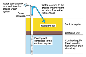
The Drain Return Package (DRT) is very similar to the regular Drain Package (DRN). Drains remove water from the aquifer as long as the water table is above the elevation of the drain. With the DRT package, some percentage of that removed water can be reintroduced to the aquifer at a specified grid cell.
DRT boundary conditions can be added to selected cells using the Point Sources/Sinks command in the MODFLOW menu. DRT objects can also be defined using the conceptual model approach in the map module.

Conceptual model
Drains can be modeled using points, arcs and/or polygons in a conceptual model. The return cell cannot be specified in the conceptual model. This is because the conceptual model is independent of the grid and, in fact, there may be no grid at all when the conceptual model is defined. When GMS performs the Map->MODFLOW command, the return cell is always set to be the highest active cell above the drain cell. This can later be changed in the Drain package dialog.
The main DRT parameters and how they can be specified are given in the following table.
| Parameter | Points | Nodes | Arcs | Polygons |
|---|---|---|---|---|
| Conductance | ||||
| Bottom elevation | ||||
| Rfprop (return-flow proportion) |
When specifying an arc as a DRT arc, the conductance and return flow factor are specified on the arc. Bottom elevation is specified at the nodes on the ends of the arc and is linearly interpolated along the length of the arc.
Care should be taken in entering conductance in the conceptual model so that the units are correct.
Drain Return package dialog
The Drain Return package dialog allows the user to edit the location and the input values associated with each drain boundary condition. Drain boundary conditions cannot be created or deleted from this dialog. They can be created and deleted via the Map -> MODFLOW command, or by using the MODFLOW Source/Sink Dialog.
The Use Return Flow toggle controls the existence of the "RETURNFLOW" optional keyword in the package input file.
Notes
- ^ Banta, Edward R. (2000), MODFLOW-2000, The U.S. Geological Survey Modular Ground-Water Model-Documentation of Packages for Simulating Evapotranspiration with a Segmented Function (ETS1) and Drains with Return Flow (DRT1). Open-File Report 00-466., Denver, Colorado, http://water.usgs.gov/nrp/gwsoftware/modflow2000/ofr00-466.pdf
| GMS – Groundwater Modeling System | ||
|---|---|---|
| Modules: | 2D Grid • 2D Mesh • 2D Scatter Point • 3D Grid • 3D Mesh • 3D Scatter Point • Boreholes • GIS • Map • Solid • TINs • UGrids | |
| Models: | FEFLOW • FEMWATER • HydroGeoSphere • MODAEM • MODFLOW • MODPATH • mod-PATH3DU • MT3DMS • MT3D-USGS • PEST • PHT3D • RT3D • SEAM3D • SEAWAT • SEEP2D • T-PROGS • ZONEBUDGET | |
| Aquaveo | ||