GMS:MODFLOW-LGR
| MODFLOW | |
|---|---|
| Pre-processing | |
| MODFLOW Commands | |
| Building a MODFLOW Model | |
| Map to MODFLOW | |
| Calibration | |
| Packages Supported in GMS | |
| Saving a MODFLOW Simulation | |
| Importing MODFLOW Files | |
| Unsupported MODFLOW Features | |
| Run MODFLOW | |
| Post-processing | |
| MODFLOW Display Options | |
| MODFLOW Post-Processing Viewing Options | |
| Reading a MODFLOW Simulation | |
| Tutorials | |
| Packages | |
| Flow: | BCF6, HUF, LPF, UPW |
| Solvers: | SMS |
| Other: | UZF1 |
MODFLOW-LGR (Local Grid Refinement) is a modified version of MODFLOW-2005 that allows for using multiple grids with different refinement.
The MODFLOW-LGR model can be added to a paid edition of GMS.
Contents
Set Up
To use MODFLOW-LGR, the user must specify this as the version in the MODFLOW Global Options dialog. If there are child grids and the user switches from MODFLOW-LGR to a different version, the child grids will be deleted.
LGR Options
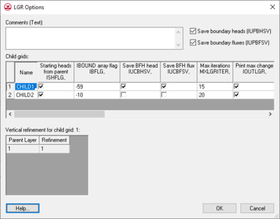
When MODFLOW-LGR is the specified version in the MODFLOW Global Options dialog, the LGR Options button becomes available. This opens the LGR Options dialog.
The items in the dialog correspond to what gets written in the LGR Control File. The child grids are listed in the upper spreadsheet. When a row is selected, the vertical refinement table lists the refinement by layer for the selected child grid. Child grids cannot be created or deleted here—that is done in the Graphics Window and the Project Explorer. They can also not be moved or have their horizontal or vertical refinement edited. All other options are editable.
Parent and Child Grids
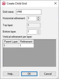
MODFLOW-LGR allows for the creation of more refined child grids in areas of particular interest. To create a child grid in GMS, you select a range of cells in the parent grid, right-click, and select the Create Child Grid menu command. This opens the Create Child Grid dialog.
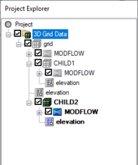
This dialog allows specifying the child Grid name, the Horizontal refinement, the Bottom layer in the parent grid, and the Vertical refinement per layer. The Top layer must always be 1, and both horizontal and vertical refinement values must be odd numbers. Child grids show up under the parent grid in the Project Explorer. Each child grid will have it's own MODFLOW model underneath it.
Active Grid and MODFLOW
There is only one active grid and MODFLOW simulation at a time. The active grid and MODFLOW icons appear in color, the inactive icons appear in grey. To switch the active grid or MODFLOW simultation, simply click on it in the Project Explorer. The main menus for the grid and MODFLOW refer to the active grid and MODFLOW simulation, and the grid tools (cell selection etc) only act on the active grid. Many dialogs in the MODFLOW interface will append "- parent" or "- child" to the dialog title to remind the user what simulation the dialog is acting on.
Ortho mode
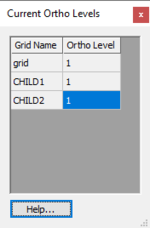
When child grids exist and the display is in ortho mode, the current grid level (row, column or layer) being viewed can be different for each grid. A setting in the 3D Grid Display Options exists called Synch ortho levels with all grids which, if on, causes GMS to display the appropriate ortho level for all grids as the active grid level changes. If this option is off, only the level of the active grid will change. To see what ortho levels are currently being displayed the user can click on the Multiple grids toggle on the Mini-Grid toolbar. This brings up the Current Ortho Levels dialog which is a modeless dialog that shows the current ortho levels being displayed on all grids. Being modeless, the dialog can be moved aside and the user can continue to interact with GMS.
Adjusting BCs Along the Boundary
As described in the LGR documentation, cells along the parent/child interface are truncated but the packages assume the full cell area. Thus adjustments should be made in these cells where DRN, EVT, GHB, RCH, or RIV packages are used. When creating a new child grid, GMS uses the equations on page 6 of the LGR documentation[1] to copy the BCs to the child grid and adjust the conductance (or recharge or evapotranspiration) in these cells. Also, when doing Map → MODFLOW the areal BCs (recharge, ET) are adjusted in border cells, but list BCs (DRN, RIV etc) are not adjusted. It is best not to have list BCs in border cells.
Running Models Independently
By default the parent and child models are run coupled when MODFLOW is executed, but they can be run independently. To run the parent or a child model independently, right-click on the model in the Project Explorer and select the Run MODFLOW Uncoupled On Just This Model command.
BFH Package
The Boundary Flow and Head (BFH) Package is unique to MODFLOW-LGR and allows for the coupled heads and flows along the parent/child border to be saved and applied when running the parent or a child independently. Use of the package is a two step process. First the models must be run coupled to calculate and save the boundary heads and flows. Then the BFH package is turned on and pointed to the saved heads or flows and a model is run independently. Turning on the option to save the boundary heads/flows is done in the LGR Options dialog. The BFH package is turned on in the usual way, using the Packages dialog. The BFH package dialog simply let's the user point to the head or flow files created during a coupled run. The BFH Package is demonstrated in the MODFLOW-LGR tutorial.
Restrictions
There are some restrictions when using MODFLOW-LGR:
- Streams created using the STR and SFR packages in GMS using the conceptual modeling approach cannot cross parent/child grid boundaries. GMS does nothing to split the stream at the model boundary and connect the parent/child stream segments.
- When child grids are present, grid editing is restricted. Splitting, merging, redistributing, and resizing grid rows, columns and layers is not allowed on child grids and not allowed in the parent grid if the rows, columns or layers intersect with a child grid.
- Parameters may be created and used but only to do a forward run, not for parameter estimation, stochastic, or stochastic inverse runs.
- MODPATH can only be used with the parent grid
MODFLOW-LGR Files
Below are tables of some of the available input and output files for MODFLOW-LGR.
- For more information on these files see the manual
|
|
External Links
Notes
- ^ Mehl, Steffen W. (2005), MODFLOW-2005, The U.S. Geological Survey Modular Ground-Water Model - Documentation Of Shared Node Local Grid Refinement (LGR) And The Boundary Flow And Head (BFH) Package. Chapter 12 of Book 6, Modeling Techniques Section A, Ground Water., Denver, Colorado, http://pubs.water.usgs.gov/tm6a12/
| GMS – Groundwater Modeling System | ||
|---|---|---|
| Modules: | 2D Grid • 2D Mesh • 2D Scatter Point • 3D Grid • 3D Mesh • 3D Scatter Point • Boreholes • GIS • Map • Solid • TINs • UGrids | |
| Models: | FEFLOW • FEMWATER • HydroGeoSphere • MODAEM • MODFLOW • MODPATH • mod-PATH3DU • MT3DMS • MT3D-USGS • PEST • PHT3D • RT3D • SEAM3D • SEAWAT • SEEP2D • T-PROGS • ZONEBUDGET | |
| Aquaveo | ||


